7-80 Draw The Shear And Moment Diagrams For The Beam
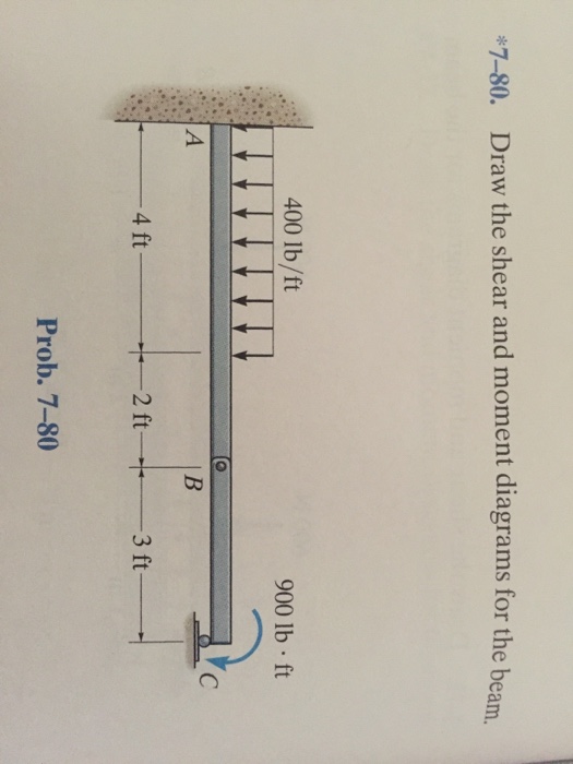
7-80 Draw The Shear And Moment Diagrams For The Beam - Web introduction figures 1 through 32 provide a series of shear and moment diagrams with accompanying formulas for design of beams under various static loading conditions. The support at a and b are a thrust and journal bearing, respectively. Web this problem has been solved! Calculate the reactions using the equilibrium equations (may not need to do this if choosing a cantilever beam and using the free side for the fbd). The bending moment diagram of the.
Shear and moment diagrams are graphical representations of the variation of shear force and bending moment along the length of a structural element such as a beam. In general the process goes like this:1) calcul. In the questions the location x proceeds from left to right! The loading, shear, and bending moment functions are: Draw the shear and moment diagrams for the beam. Draw the shear and moment diagrams for the beam. You'll get a detailed solution from a subject matter expert that helps you learn core concepts.
Solved *780. Draw the shear and moment diagrams for the
In the questions the location x proceeds from left to right! Web using the moment distribution method, determine the end moments and the reactions at the supports of the beam shown in figure 12.7a. Shear.

Drawing Shear and Moment Diagrams for Beam YouTube
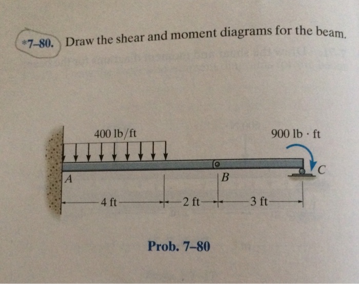
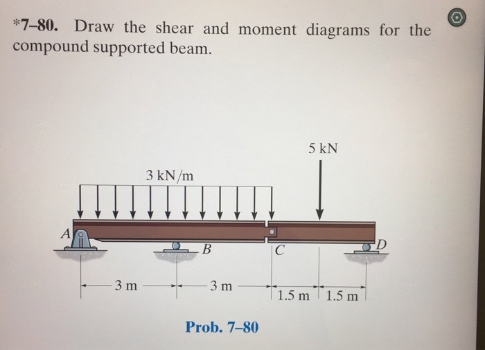
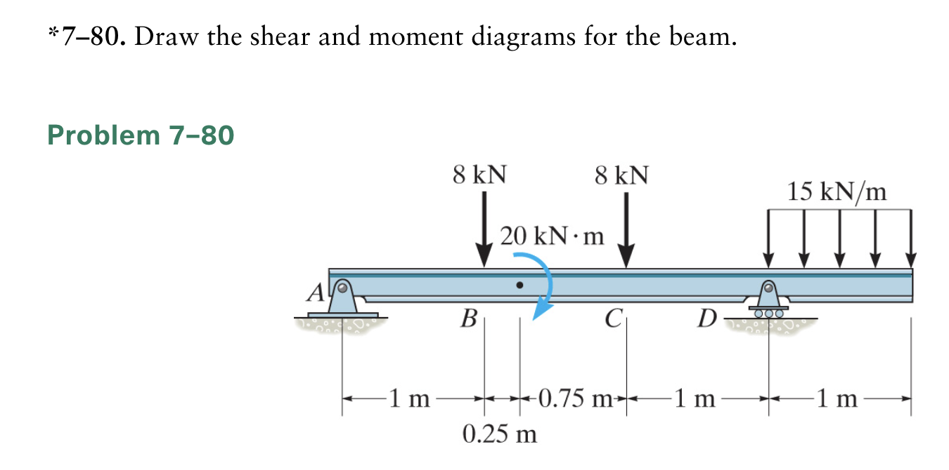
We are asked to draw the shear and moment diagrams for the beam. Draw the shear and moment diagrams for the beam. Also, draw shear and moment diagrams, specifying values at all change of loading.

Solved Draw the shear and moment diagrams for the beam, and
In addition to the two principal values of bending moment at x = 0 m and at x = 5 m, the moments at other intermediate points should be determined to correctly draw the bending.

Solved Draw the shear and moment diagrams for the beam.
We are asked to draw the shear and moment diagrams for the beam. Web you’ll understand how to model beam elements that resist axial force, shear forces and bending moments within the direct stiffness method..
Solved 780. Draw the shear and moment diagrams for the
Here’s the best way to solve it. Web using the moment distribution method, determine the end moments and the reactions at the supports of the beam shown in figure 12.7a. Also, draw shear and moment.

Draw the shear and moment diagrams for the beam.
Web introduction figures 1 through 32 provide a series of shear and moment diagrams with accompanying formulas for design of beams under various static loading conditions. Web since the function for the bending moment is.
Solved 780. Draw the shear and moment diagrams for the
Skyciv beam tool guides users along a professional beam calculation workflow, culminating in the ability to view and determine if they comply with your region's design codes. The loading, shear, and bending moment functions are:.
Solved *780. Draw the shear and moment diagrams for the
This page will walk you through what shear forces and bending moments are, why they are useful, the procedure for drawing the diagrams and some other keys aspects as well. Draw the shear and moment.

Learn How To Draw Shear Force And Bending Moment Diagrams Engineering
Web introduction figures 1 through 32 provide a series of shear and moment diagrams with accompanying formulas for design of beams under various static loading conditions. Web you’ll understand how to model beam elements that.

Learn How To Draw Shear Force And Bending Moment Diagrams Engineering
Web this video explains how to draw shear force diagram and bending moment diagram with easy steps for a simply supported beam loaded with a concentrated load. Web since the function for the bending moment.
7-80 Draw The Shear And Moment Diagrams For The Beam In each problem, let x be the distance measured from left end of the beam. We are asked to draw the shear and moment diagrams for the beam. Web draw the shear force and bending moment diagrams for the cantilever beam supporting a concentrated load of 5 lb at the free end 3 ft from the wall. Web you’ll understand how to model beam elements that resist axial force, shear forces and bending moments within the direct stiffness method. Web the first step in calculating these quantities and their spatial variation consists of constructing shear and bending moment diagrams, \(v(x)\) and \(m(x)\), which are the internal shearing forces and bending moments induced in.