An Engineering Drawing Shows The
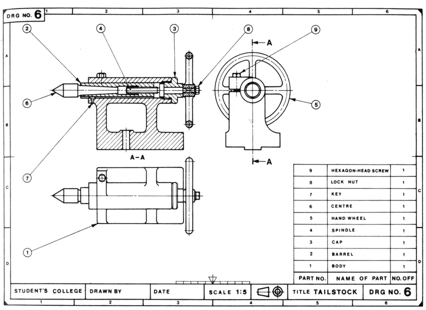
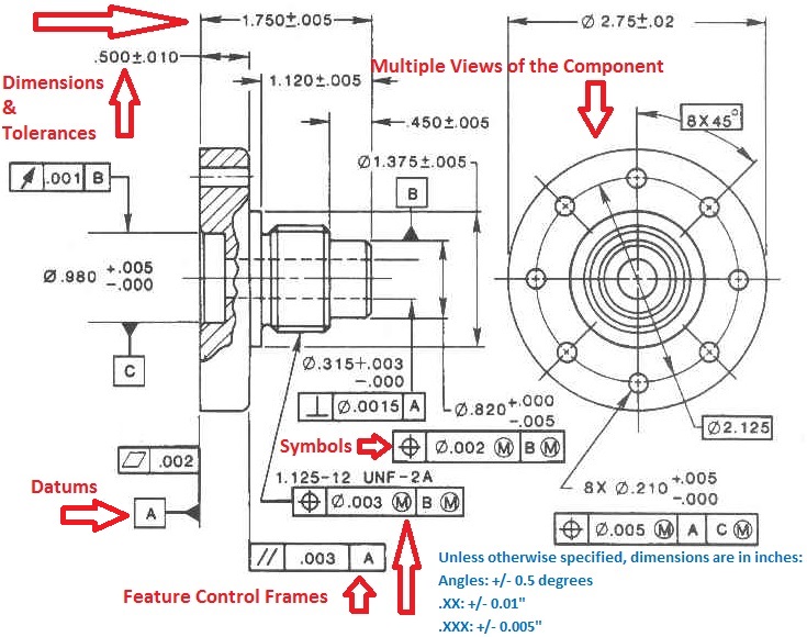
An Engineering Drawing Shows The - A complete understanding of the object should be possible from the drawing. Web an engineering drawing (also named as mechanical drawing, manufacturing blueprints, drawings, dimensional prints, and more) refers to one of the technical drawings, which helps to define engineering products’ requirements. Engineering drawings use standardised language and symbols. Dimensions, tolerances, materials, and finishes of a component. Usually, a number of drawings are necessary to completely specify even a simple component.
Engineering drawings are more than just drawings—they’re detailed illustrations that show all the information and specifications required to build a part using a standard format and terminology. Engineering drawings are also known as mechanical drawings, manufacturing blueprints and drawings. Sometimes using main orthographic views is impossible to show all the features of an object to the degree that the object is. Web engineering drawing, often referred to as technical or mechanical drawing, is the universal language of engineers and technicians. Web an engineering drawing is a visual representation of a product, its parts and assemblies, and its dimensions. Web any engineering drawing should show everything: Sometimes, you will have to place dimensions in two units simultaneously!

Mechanical Engineer Drawing at GetDrawings Free download
Engineering drawings are more than just drawings—they’re detailed illustrations that show all the information and specifications required to build a part using a standard format and terminology. Web october 14, 2022 / 10 minutes of.

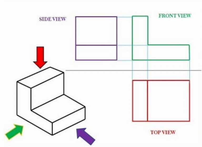
Engineering Drawing Tutorials/Orthographic and sectional views ( T 11
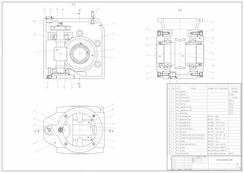
(d) cost, materials, tolerances, and lead. The purpose is to convey all the information necessary for manufacturing a product or a part. Cylindrical objects are usually shown in two view drawings and include one view.

How to prepare a technical drawing for CNC machining Hubs
Materials, finishes, machining operations, and dimensions of a component d. Engineering drawings use standardised language and symbols. (c) materials, finishes, machining operations, and dimensions of a component. You'll get a detailed solution from a subject.

Pin on Dibujos Tecnicos
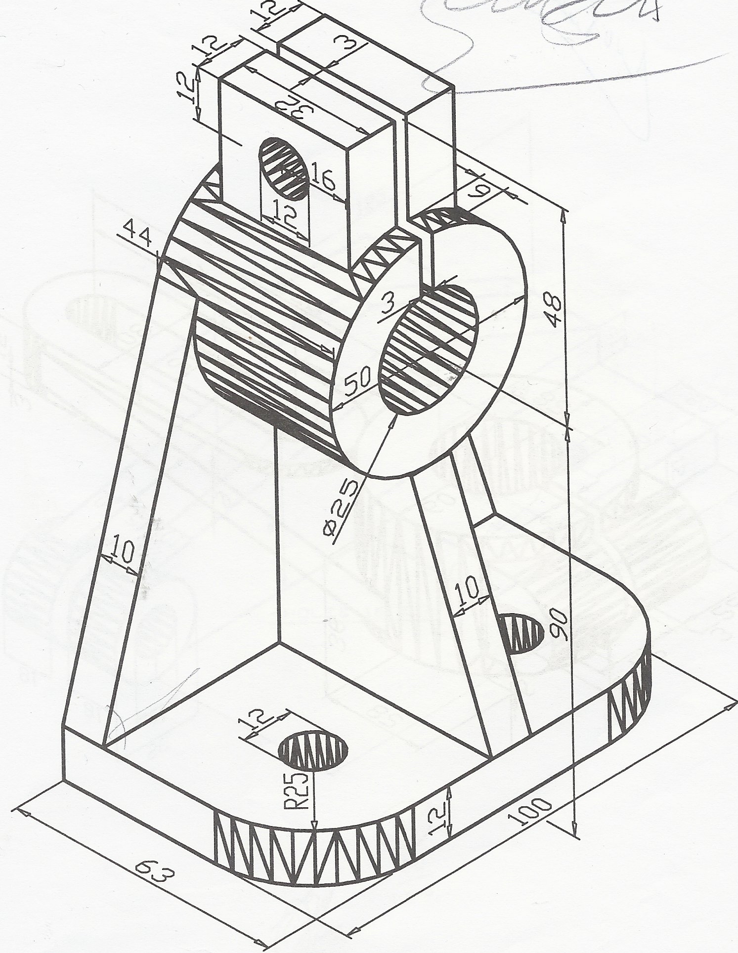
If the isometric drawing can show all details and all dimensions on one drawing, it is ideal. This makes understanding the drawings simple with little to no personal interpretation possibilities. Engineering drawings are also known.
Download How To Read Basic Engineering Drawing Guide Pictures
An engineering drawing shows the: This problem has been solved! Engineering drawings are used to guide the design process and manufacturing process of new products or repairs. An engineering drawing shows the: Working drawings are.
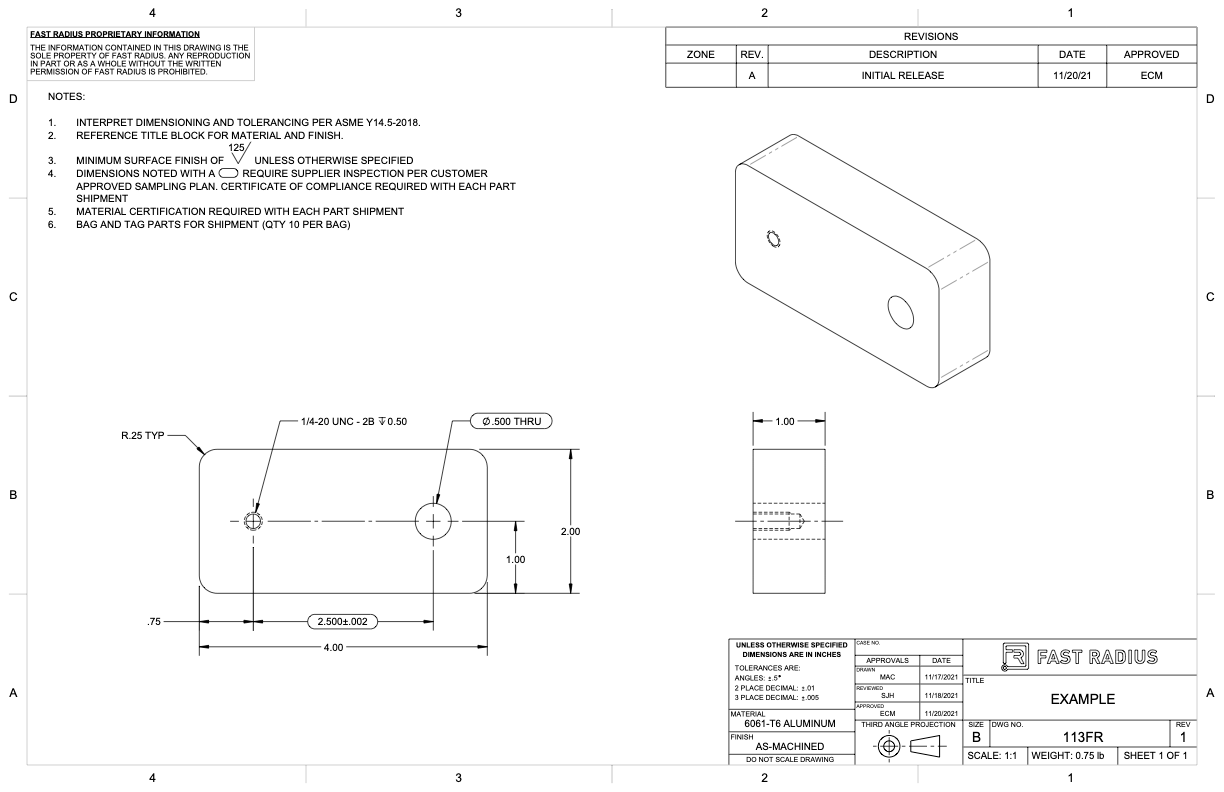
What to Include in Your Engineering Drawing Fast Radius
Web in engineering drawing , the postion that normally shows the most details of something, regardless of whether it is actually the front of the object. Working drawings are the set of technical drawings used.
Engineering Drawing Views & Basics Explained Fractory
The purpose is to convey all the information necessary for manufacturing a product or a part. Materials, finishes, machining operations, and dimensions of a component. Engineering drawings use standardised language and symbols. A complete understanding.
Engineering Drawing Views & Basics Explained Fractory
Dimensions, tolerances, cost, and sales or use volume of a component c. Web answered • expert verified. Dimensions should be placed in the most descriptive view of the feature. Web the common metric unit of.
Lecture Notes Engineering Drawing Part 5
(a) dimensions, tolerances, cost, and sales or use volume of a component. Dimensions should be placed in the most descriptive view of the feature. (c) materials, finishes, machining operations, and dimensions of a component. Web.
Engineering Drawings & GD&T For the Quality Engineer
Web the common metric unit of measure on engineering drawings is the millimeter, abbreviated as mm. Web an engineering drawing is a subcategory of technical drawings that show the shape, structure, dimensions, tolerances, accuracy and.
An Engineering Drawing Shows The Web an engineering drawing shows the: Dimensions should be placed in the most descriptive view of the feature. Web the common metric unit of measure on engineering drawings is the millimeter, abbreviated as mm. Engineering drawings use standardised language and symbols. Web in introduction to engineering drawings, we showed you the building blocks of engineering drawing.