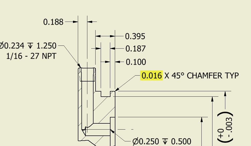
Chamfer Callout Drawing
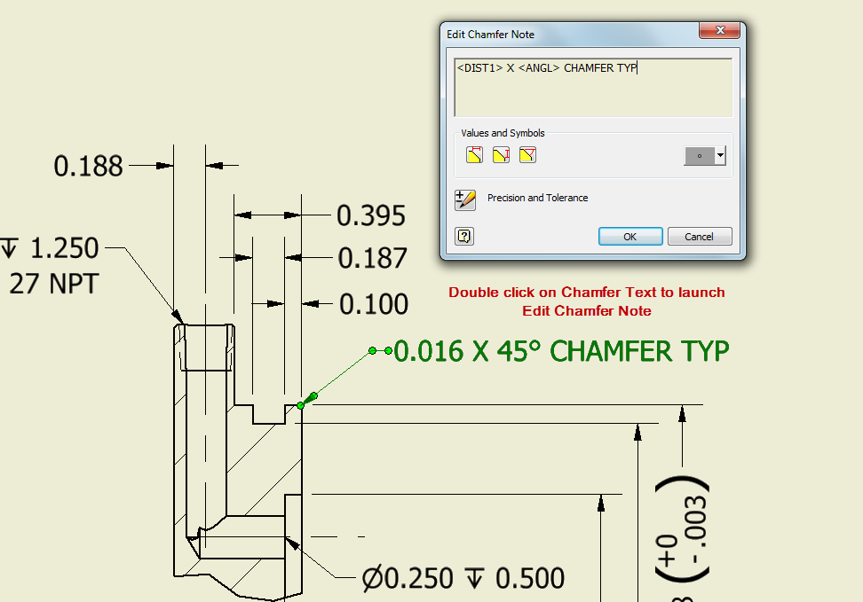
Chamfer Callout Drawing - Is the correct callout for this 2x 0.031 x 45° or does each chamfer need to be noted individually? Is it to call out the note with a leader (.25 x 45°) or to add two seperate dimensions (one linear and chamfer callout? If machinery has screw holes or screws they must be dimensioned properly. For structural i have previously. Click chamfer dimension on the dimensions/relations toolbar or click tools > dimensions > chamfer.
You can also click legacy sketch > chamfer. You just need to give the length of one edge and the corresponding angle to it. Web dimensioning chamfers is done with a call out that specifies the length of the chamfer along with the angle of the chamfer. After drawing the part, from the menu bar select design > solid > modify > chamfer. Then select one of the lines at the end of your chamfer, then select the line of the edge of the chamfer. Threads are the major geometrical shapes of screws and screw holes. S —surface form can be called out on a drawing in one of two ways.
Inventor Ability to change the decimal places in the call out of the
Web to insert chamfer dimensions into a drawing: Web since threading often produces starting burrs, these can be minimized by specifying a 45° countersink or chamfer which is.015″ minimum larger than the major diameter on.
Inventor Ability to change the decimal places in the call out of the
Click chamfer dimension on the dimensions/relations toolbar or click tools > dimensions > chamfer. Then select one of the lines at the end of your chamfer, then select the line of the edge of the.

SolidWorks Tutorial How to Add Chamfer Dimension In Solidworks Drawing
You must select the chamfered edge first. Select a circle that is part of a hole feature, or a thread that is part of an external thread feature. The select dialog box opens. To continue.
Solved Multiple chamfers on drawings PTC Community
Threads are the major geometrical shapes of screws and screw holes. .040 x 30) to my knowledge the.040 be the depth into the material and the 30 degrees is the angle from the centerline. Web.

How to interpret the values of a chamfer and a thread in a blueprint
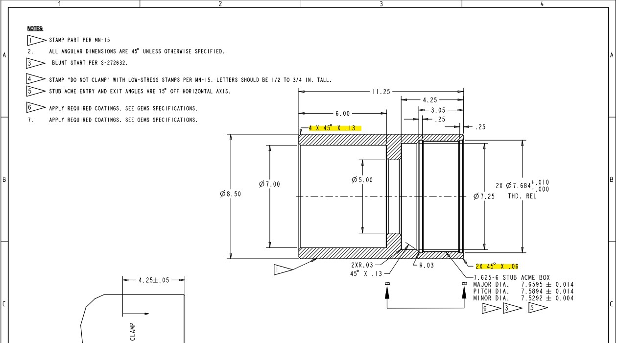
To continue from the aforementioned thread, how would i call out multiple chamfered corners? Is it to call out the note with a leader (.25 x 45°) or to add two seperate dimensions (one linear.
Dimensioning standards
Web to insert chamfer dimensions into a drawing: Web may 5, 2022 by brandon fowler learning to read blueprints can be hard. You must select the chamfered edge first. This opens the chamfer dialog box..

Adding a Chamfer Dimension YouTube
You just need to give the length of one edge and the corresponding angle to it. Web a chamfer callout on this platform is straightforward with the steps as follows: Web basic dimensioning introduction dimensioning.
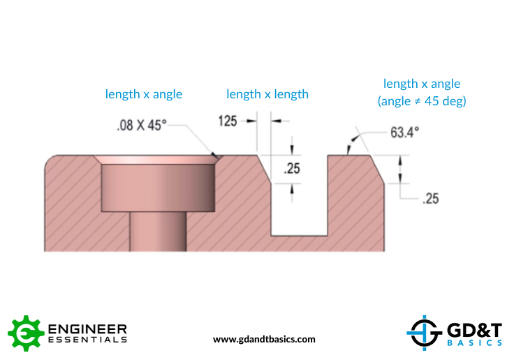
Chamfer Dimensioning GD&T Basics
Web since threading often produces starting burrs, these can be minimized by specifying a 45° countersink or chamfer which is.015″ minimum larger than the major diameter on internal threads (see figure 4) and.015″ minimum smaller.

Dimensioning Chamfers YouTube
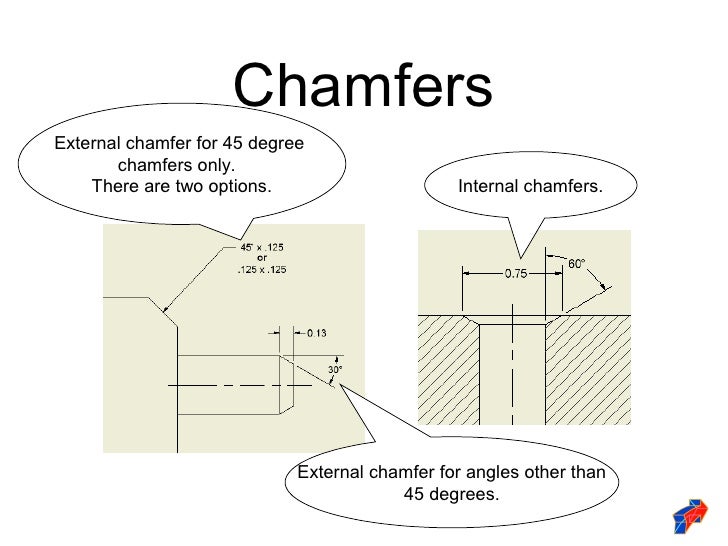
If no angle is given the chamfer is assumed to be at 45 degrees. At times, the break edge specification may be contained in the general tolerance block such as shown below. Web what is.
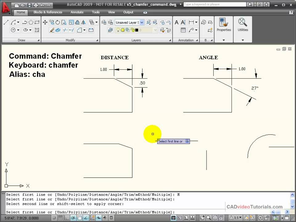
AutoCAD Tutorial Using the CHAMFER Command YouTube
Then select one of the lines at the end of your chamfer, then select the line of the edge of the chamfer. All of the basic components of an engineering drawing are detailed below with.
Chamfer Callout Drawing After drawing the part, from the menu bar select design > solid > modify > chamfer. For structural i have previously. If the selection was part of a hole feature, the precision, tolerance, fit class tolerance, and shaft class tolerance values from that feature are automatically applied. Select the first chamfer reference, such as a point on a model edge or draft entity. The select dialog box opens.