Design A 8-Bit Full Adder. Draw The Block Diagram.
Design A 8-Bit Full Adder. Draw The Block Diagram. - Web expert answer transcribed image text: Web it has two input terminals and two output terminals for sum (s) and carry (c). In the half adder, the output of the xor gate is the sum of two bits and the. Web discuss courses bcd stands for binary coded decimal. Adder xor rangkaian ripple transistor pengertian kombinasiadder ic bit 7483 using binary parallel adders explain four design and explain 8 bit binary adder using ic 7483.adder bcd 7483 ic using digit circuit output.
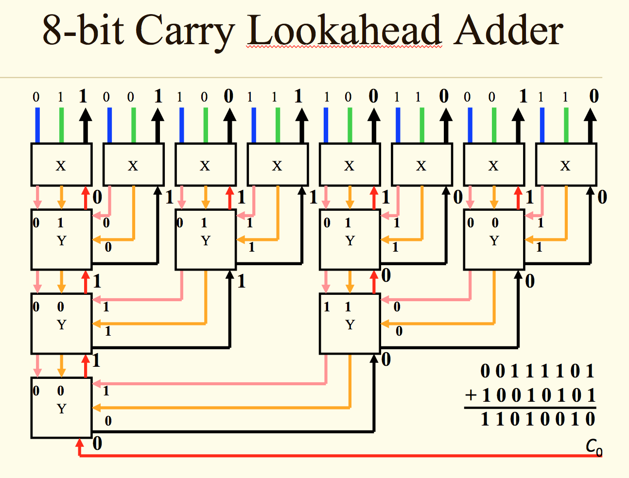
There are 2 steps to solve this one. Entity fa_8bit is port(x,y : Steps involved are as follows: Web to facilitate this, layout a one bit slice of the circuit first and then assemble 8 of them to make the 8 bit adder. Identify the advantages and disadvantages of the iterative cell method. It uses several full adders in cascade. Web full adder is a combinational logic circuit used for the purpose of adding two single bit numbers with a carry.
8 Bit Adder Circuit
It is used to perform the addition of bcd numbers. Create a new schematic diagram & save it as fa.bdf . The first half adder circuit is on the left side, we give two single.

Block diagram of an 8bit carry select adder Download Scientific Diagram
2.) draw the circuit for the following boolean expression: Web full adder is a combinational logic circuit used for the purpose of adding two single bit numbers with a carry. This problem has been solved!.

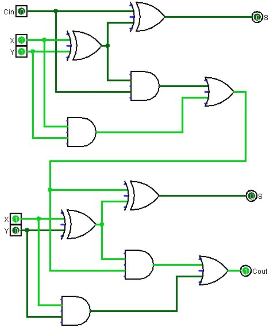
CircuitVerse 8 bit Full Adder/Subtractor
(10.5 marks) (i) draw the logic symbol (block diagram) of full adder and label all inputs and outputs clearly. Web this problem has been solved! It produces both a sum and a carry output. Entity.
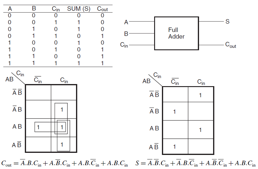
Full Adder Electronics Tutorial
A single full adder is used to add one pair of bits at a time along with the carry. Web to facilitate this, layout a one bit slice of the circuit first and then assemble.
![[DIAGRAM] 8 Bit Adder Circuit Diagram](http://1.bp.blogspot.com/-2wgYeWKzJ8I/UiS9J5Qgx8I/AAAAAAAAAAg/uIHVAWi6uUQ/s1600/ripple-adder.png)
[DIAGRAM] 8 Bit Adder Circuit Diagram
A single full adder is used to add one pair of bits at a time along with the carry. It is also a circuit used in electronics and digital logic design and is used to.
8 bit full adder truth table vilaviation
It is used to perform the addition of bcd numbers. Web computer science questions and answers. With this design information we can draw the bcd adder block diagram, as shown in the fig. Create a.

Design an 8bit Adder Using Two 4bit Adders Lagrange Alses1994
(iii) use the full adder diagram, design an. This adder can be converted to half subtractor by adding an inverter. Two shift registers are used to store the binary numbers that are to be added..

CircuitVerse 8 Bit Full Adder and Subtractor
Web serial binary adder performs bit by bit addition. The first half adder circuit is on the left side, we give two single bit binary inputs a and b. Full adder circuit diagramadder bcd 7483.

Design 8bit BCD.
The value of a and b can vary from 0 (0000 in binary) to 9 (1001 in binary) because we are considering decimal. It is used to perform the addition of bcd numbers. Web 20+.
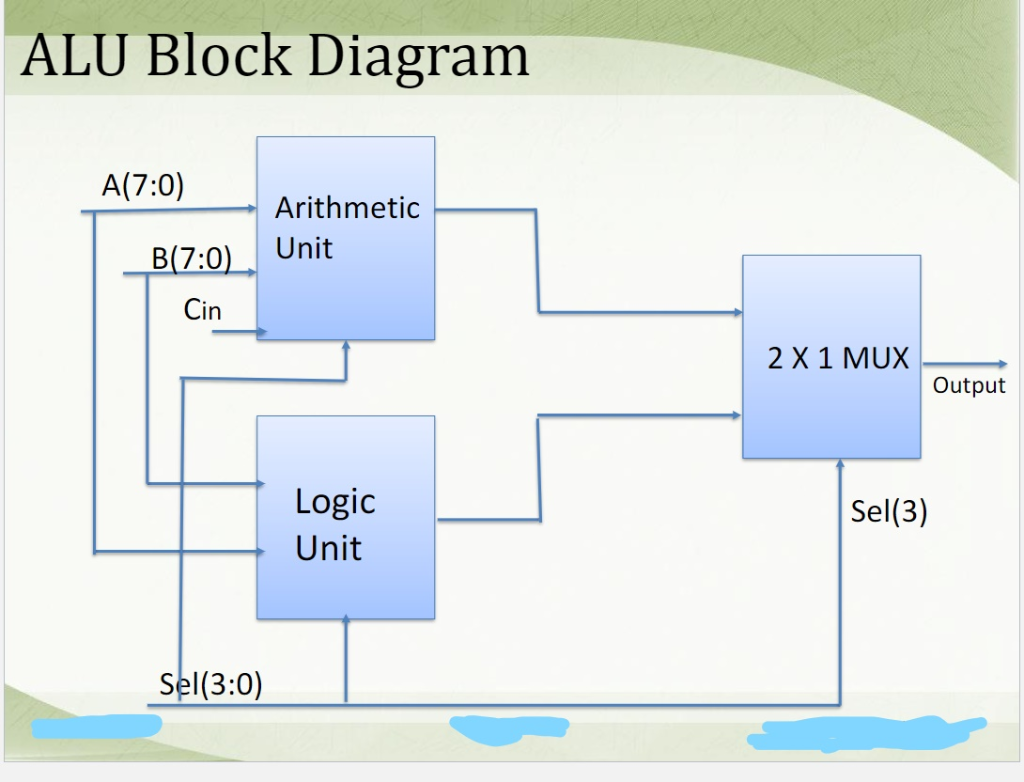
Solved Design an 8 bit ALU using an 8 bit adder, 8 bit
Web 20+ full adder block diagram. Their most common application is in the form of arithmetic logic units (alus). Create a new project with the name lab4 . A single full adder is used to.
Design A 8-Bit Full Adder. Draw The Block Diagram. As seen in the previous half adder tutorial, it will produce two outputs, sum and carry out. This adder can be converted to half subtractor by adding an inverter. Web computer science questions and answers. Adder xor rangkaian ripple transistor pengertian kombinasiadder ic bit 7483 using binary parallel adders explain four design and explain 8 bit binary adder using ic 7483.adder bcd 7483 ic using digit circuit output. Half adder and full adder.