Draw Logic Gate
Draw Logic Gate - Web the logic gate usually describes the conditions for the current flow you are using as a switch. Web a free, simple, online logic gate simulator. Navigate to [new]> [electrical engineering]> [circuits and logic] step 3: The following types of logic gates are commonly used: The result is a logic circuit.
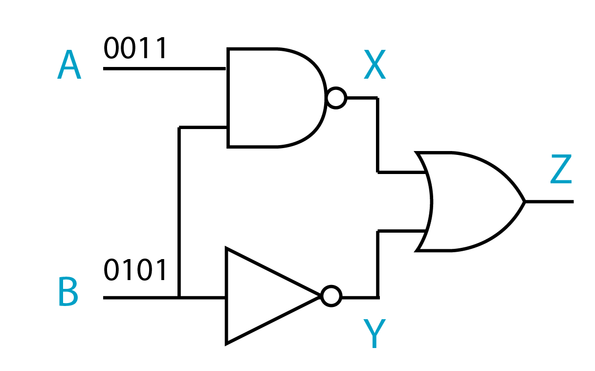
Web in this post you will practise drawing logic gates diagrams using the following logic gates: These gates are implemented using electronic switches like. Web the logic gate, which gives a high output (i.e., 1) if either input a or input b but not both are high (i.e. Web a logic gate is a device that performs a boolean function, a logical operation performed on one or more binary inputs that produces a single binary output. Right click connections to delete them. In this video, i'm going to show how to use a free online diagramming tool diagrams.net (draw.io). And, or, xor, not, nand, nor and xnor.

Drawing Logic Gates From Boolean Expressions Important Questions 4
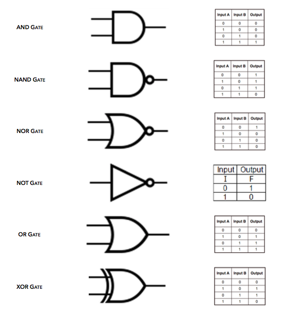
There are several different types of logic gates, including and, or, and not gates. The following illustration and table show the circuit symbol and logic combinations for an and gate. In this video, i'm going.
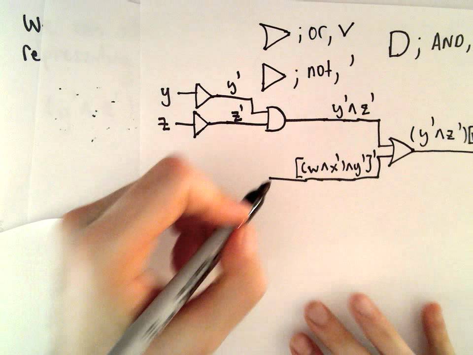
Logical Gates ( Drawing a Circuit that Corresponds to a Boolean
First you will need to learn the shapes/symbols used to draw the four main logic gates: From simple gates to complex sequential circuits, plot timing diagrams, automatic circuit generation, explore standard ics, and much more.
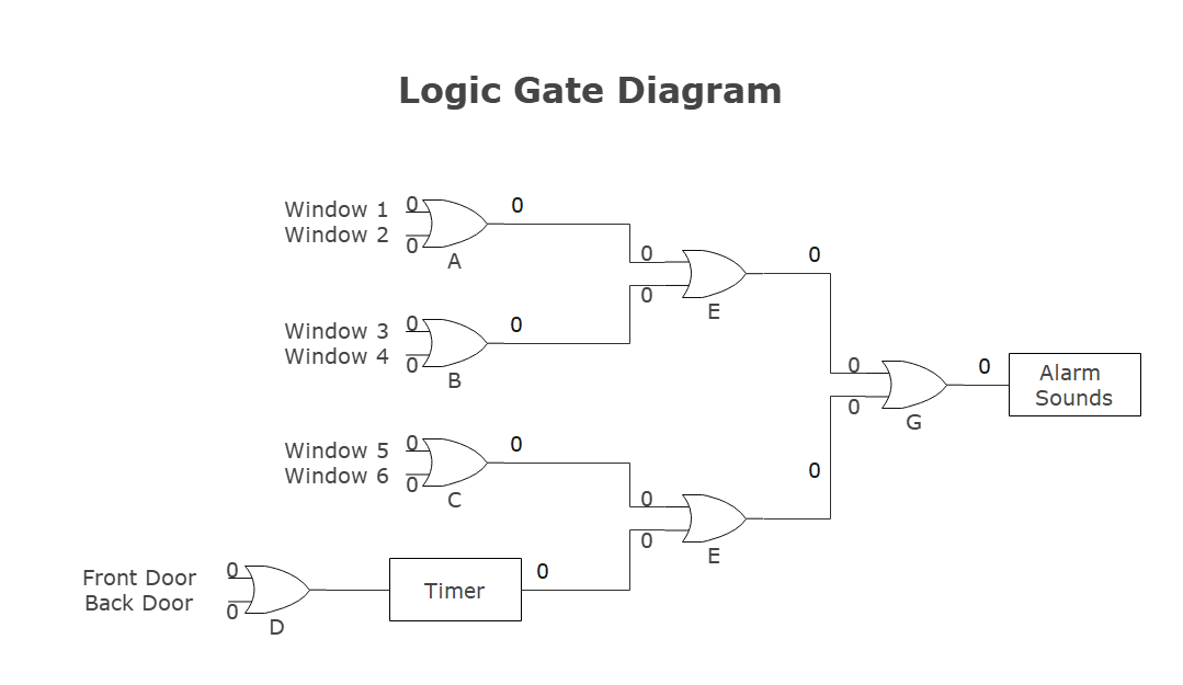
Diagram Of Logic Gates
Web there are seven basic logic gates: Web the first step in drawing a logic gate circuit is to determine what type of logic gate you need. You can design and test your own circuits.
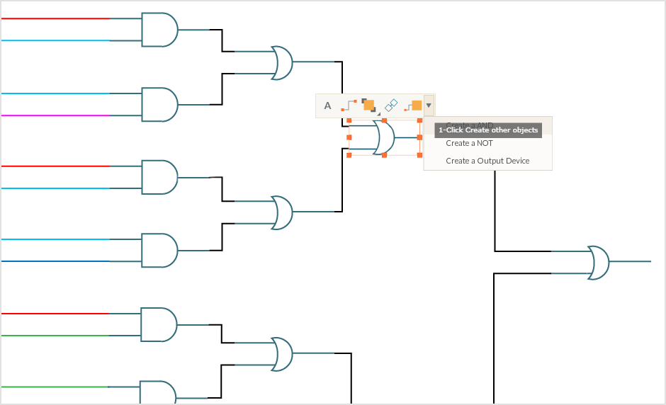
Logic Gate Drawing Tool Learn Diagram
1), is called the exclusive or gate or the xor gate. With logic gates, you can perform various binary operations such as addition, multiplication, and division. Select gates from the dropdown list and click add.

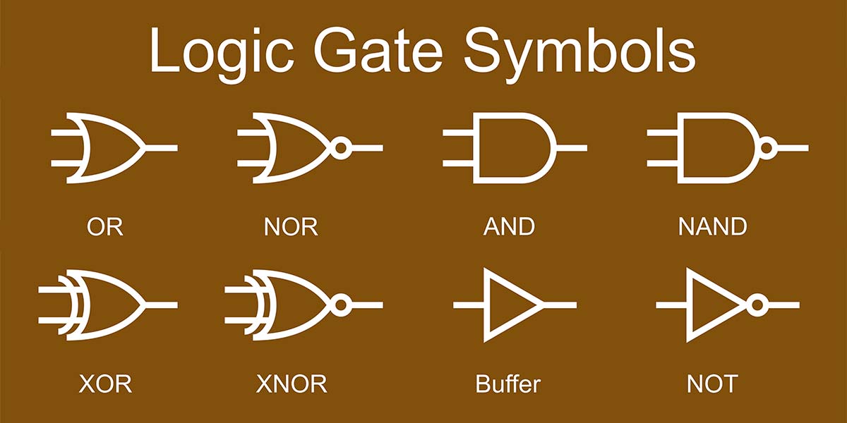
Logic Gates Symbol CAD Block And Typical Drawing For Designers
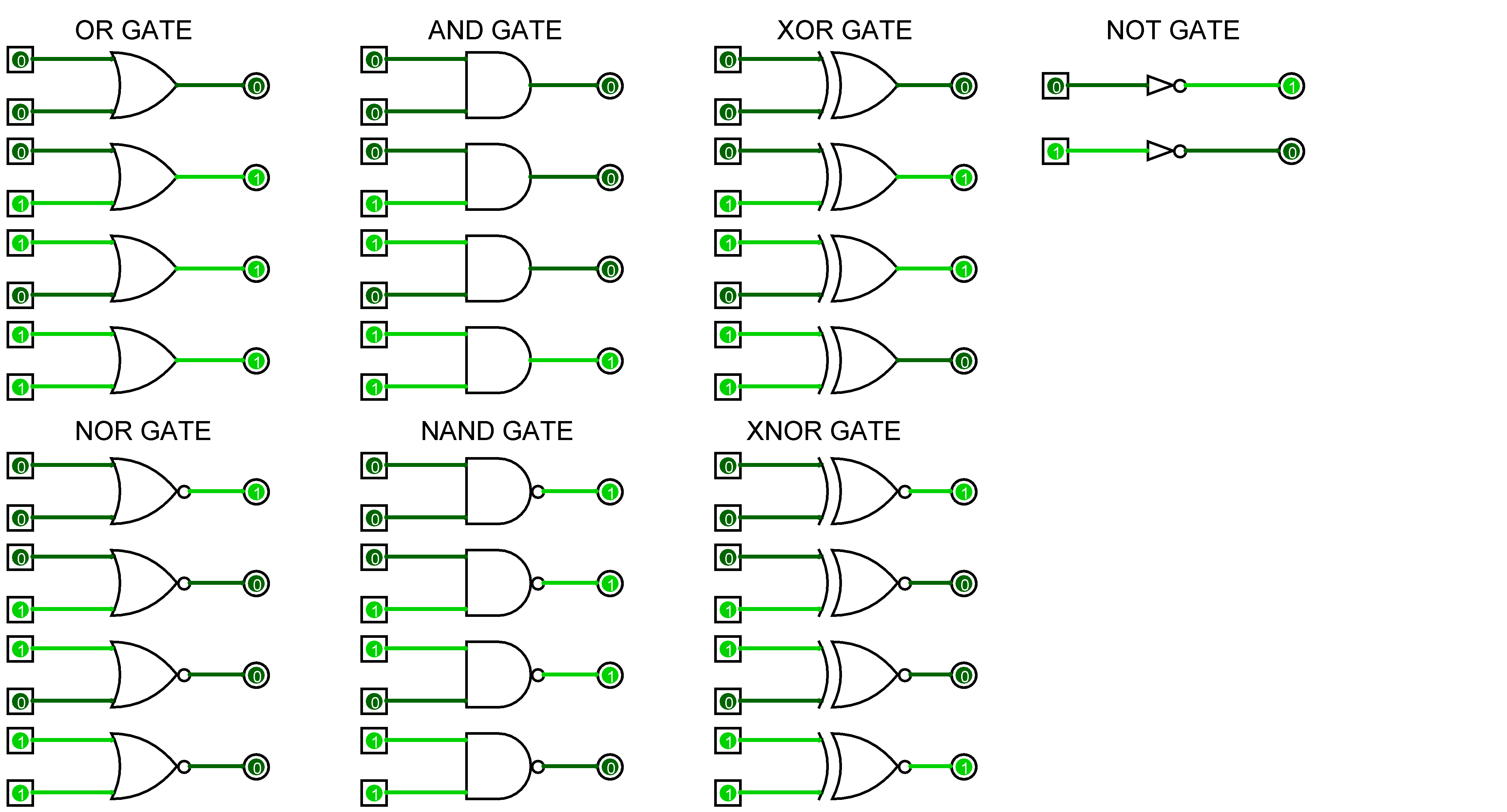
These are the seven basic logic gates, and, or, not, nand, nor, xnor, xor. What are the seven logic gate? Web a logic gate is a device that performs a boolean function, a logical operation.
Logic Gate Circuit Diagram Examples Wiring Diagram Schemas
Web the logic gate, which gives a high output (i.e., 1) if either input a or input b but not both are high (i.e. The logic circuit in the figure has three inputs, labeled a,.
Logic Gates Combination of Logic Gate SPM Physics Form 4/Form 5
In logic gates, we consider 1 to be true and 0 to be false. For math, science, nutrition, history, geography, engineering, mathematics, linguistics, sports, finance, music… Drag from the hollow circles to the solid circles.
xor gate diagram
Logic gates, use logic to determine whether or not to pass a signal. Web since the inputs and outputs of logic gates are just wires carrying on/off signals, logic gates can be wired together by.
![[Solved] How to draw logic gates in tikz 9to5Science](https://i.stack.imgur.com/ut5wE.png)
[Solved] How to draw logic gates in tikz 9to5Science
First you will need to learn the shapes/symbols used to draw the four main logic gates: Right click connections to delete them. There are several different types of logic gates, including and, or, and not.
Circuit Diagram Logic Gates
Web a logic gate is a digital gate that allows data to be transferred. Web the logic gate, which gives a high output (i.e., 1) if either input a or input b but not both.
Draw Logic Gate The relationship between the i/p and the o/p is based on a certain logic. What are the seven logic gate? We also had a brief look at logic gates as used in computer code. With logic gates, you can perform various binary operations such as addition, multiplication, and division. Select gates from the dropdown list and click add node to add more gates.