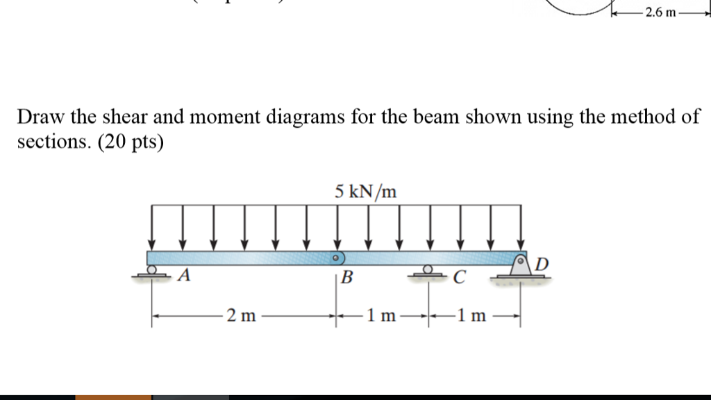
Draw The Shear And Moment Diagrams For The Beam Shown
Draw The Shear And Moment Diagrams For The Beam Shown - Web a bending moment diagram is one which shows variation in bending moment along the length of the beam. If l=9 m, the beam will fail when the maximum shear force is vmax=5kn or the. Advanced physics questions and answers. Let a = 5.0 ft, b = 4.5 ft, p = 21 kips, and w = 3.0 kips/ft. Shear and moment diagrams and formulas are excerpted from the western woods use book, 4th edition, and are provided herein as a courtesy of western wood.
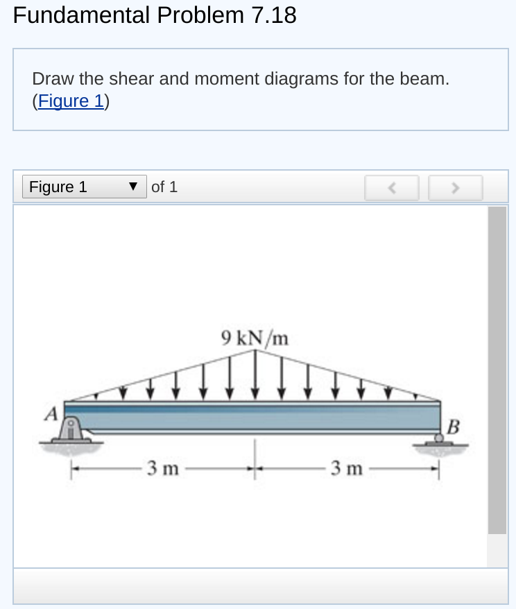
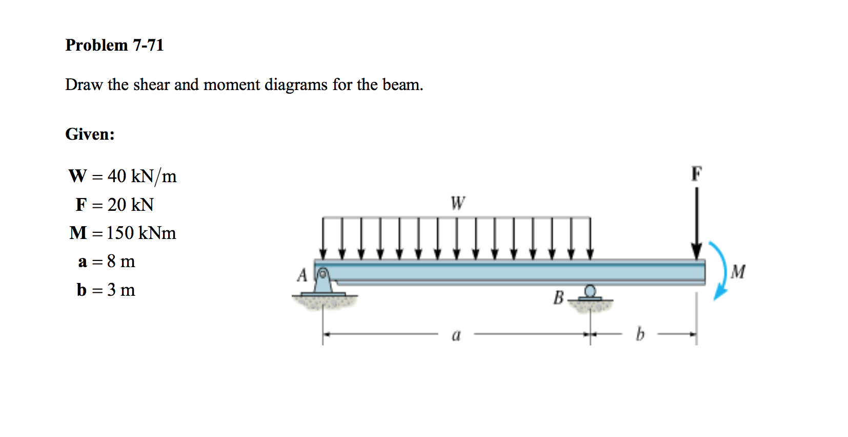
Web step 1 | draw a free body diagram. Determine the maximum value of (a) the internal shear force and (b) the internal bending. Also, draw the shear force diagram (sfd) and the bending moment diagram (bmd). Draw the shear and moment diagrams for the beam. Web draw the shear and moment diagrams for the beam. Free body diagram b a 40kn/m 20 kn 8 m 3 m 150 kn.m view the full answer step 2 step 3 step 4 final answer Web in general the process goes like this:1) calcul.

Solved Draw the shear and moment diagrams for the beam (a)
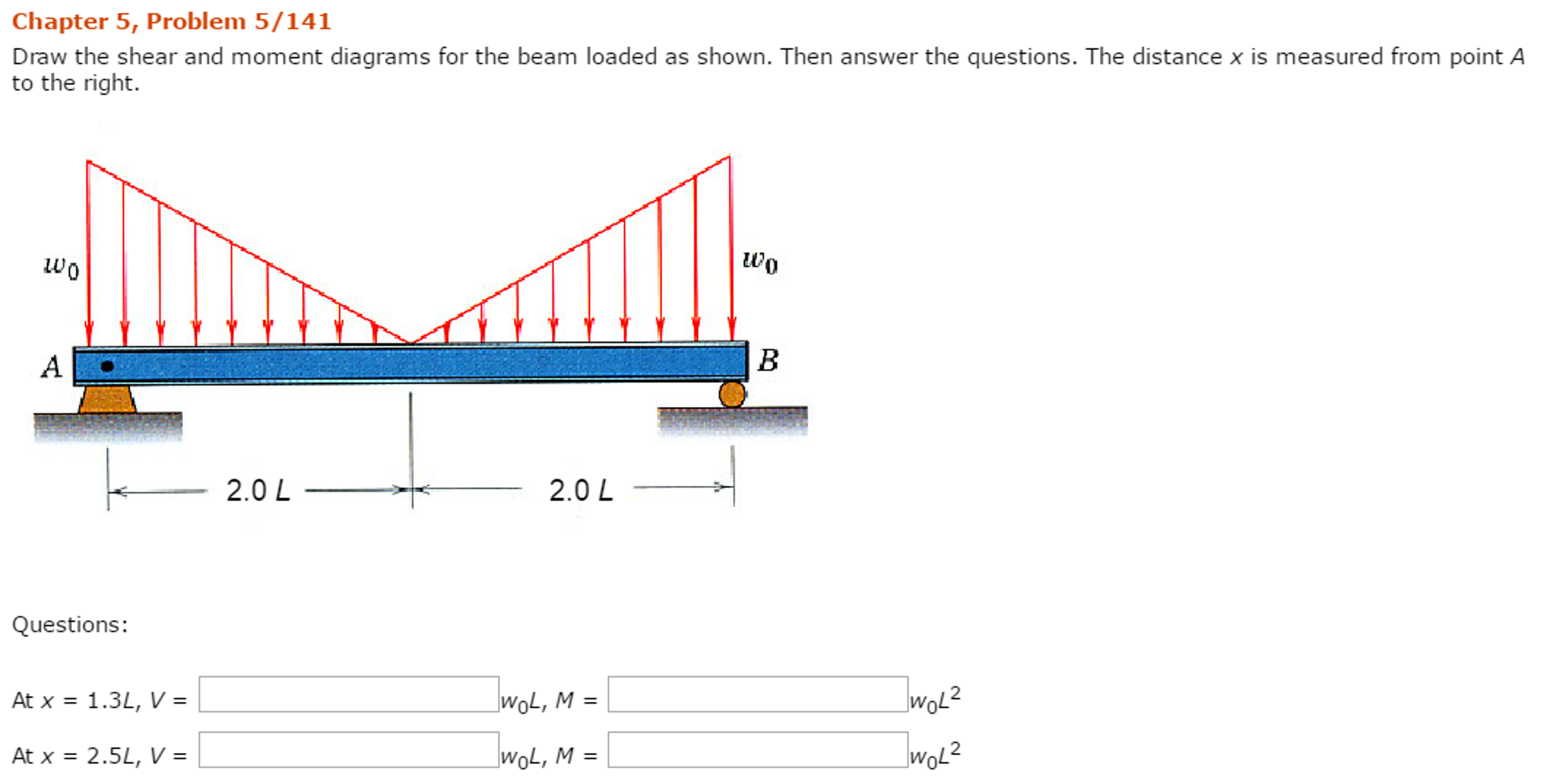
∑ m = 0 ; Web introduction figures 1 through 32 provide a series of shear and moment diagrams with accompanying formulas for design of beams under various static loading conditions. Web the shear force.
Solved Draw The Shear And Moment Diagrams For The Beam Sh...
Web step 1 | draw a free body diagram. Web the shear force and the bending moment usually vary continuously along the length of the beam. Draw the shear and moment diagrams of the beam.
Solved Draw the shear and moment diagrams for the beam
You'll get a detailed solution from a subject matter expert that helps you learn core concepts. This problem has been solved! Web in general the process goes like this:1) calcul. Draw the shear and moment.

Solved Draw the shear and moment diagrams for the beam.
The reactions shown on the diagram are determined from equilibrium equations as follows: Let a = 5.0 ft, b = 4.5 ft, p = 21 kips, and w = 3.0 kips/ft. 20 kn 40 kn/m.
Solved Draw the shear and moment diagrams for the beam.
Web shear force and bending moment diagrams are analytical tools used in conjunction with structural analysis to help perform structural design by determining the value of shear forces and bending moments at a given point.
Solved Draw the Shear and Moment Diagram for the beam shown
Advanced physics questions and answers. You'll get a detailed solution from a subject matter expert that helps you learn core concepts. ∑ m = 0 ; (a) draw complete shear and moment diagrams (b) design.

Shear and moment diagrams geekloki
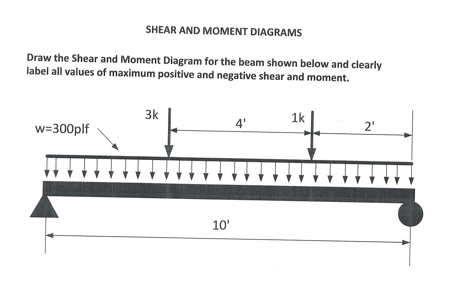
Label all significant points on each diagram. You'll get a detailed solution from a subject matter expert that helps you learn core concepts. Let a = 5.0 ft, b = 4.5 ft, p = 21.
Solved Draw the shear and moment diagrams for the beam.
1) calculate the shear force and bending moment for the beam subjected to concentrated load as shown in the figure. Web the shear force and the bending moment usually vary continuously along the length of.

Learn How To Draw Shear Force And Bending Moment Diagrams Engineering
(a) draw complete shear and moment diagrams (b) design the cross section of the beam, knowing that the grade of timber used has an allowable normal stress of 1,200psi and an allowable shear stress of.

Solved Draw the shear and moment diagrams for the beam, and
Label all significant points on each diagram. 1) calculate the shear force and bending moment for the beam subjected to concentrated load as shown in the figure. In each problem, let x be the distance.
Draw The Shear And Moment Diagrams For The Beam Shown 250 lb 25011 150 4 ft oft this problem has been solved! Web draw the shearing force and bending moment diagrams for the beam with an overhang subjected to the loads shown in figure 4.8a. Advanced physics questions and answers. Web in general the process goes like this:1) calcul. (1) normal stress that is caused by bending moment and.