Draw The Shear And Moment Diagrams For The Simply-Supported Beam
Draw The Shear And Moment Diagrams For The Simply-Supported Beam - Draw the shear and moment diagram. Web draw the shear and moment diagrams for the simply supported beam. Draw the shear and moment diagrams for the simply supported beam. View the full answer step 2 unlock answer unlock previous question next question not the question you’re looking for? In a simply supported beam, the only vertical force is the 5kn/m force, which when multiplied by the length of the member (l = 10) we get 5*10 = 50 kn.
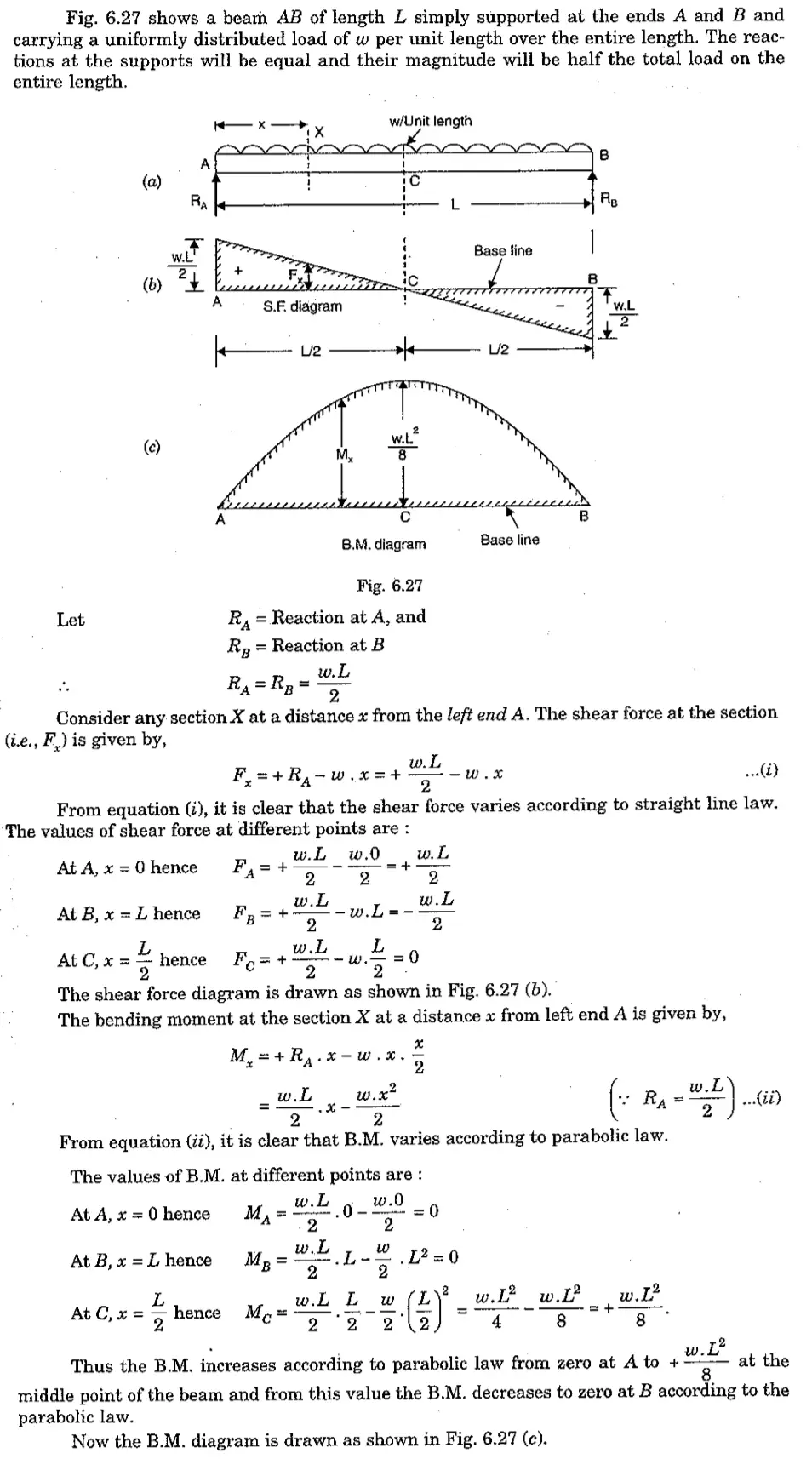
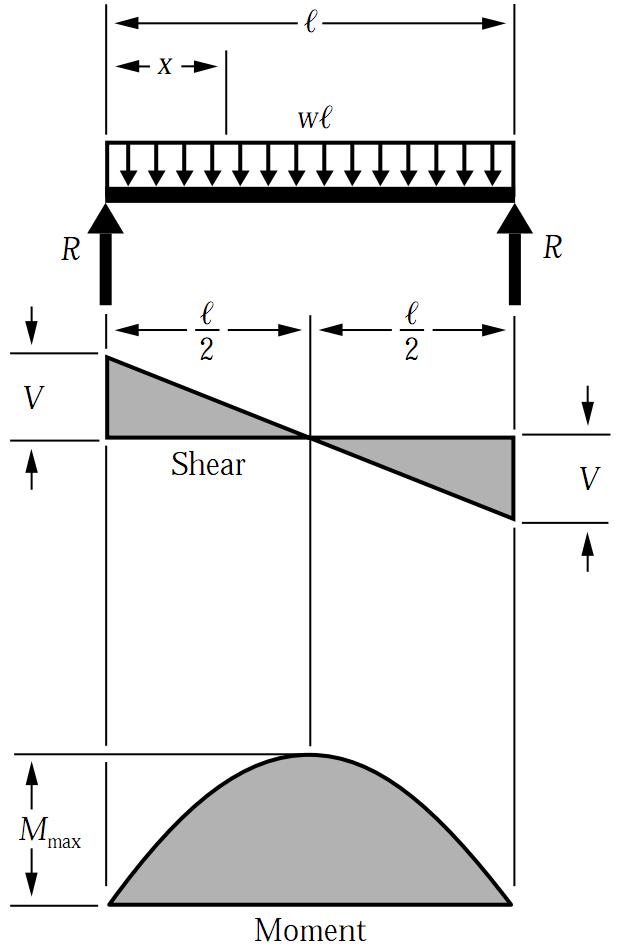
Draw the shear and moment diagrams for the simply supported beam draw the shear and moment diagrams for the simply. Web let the shear force and bending moment at a section located at a distance of x from the left support be v and m, respectively, and at a section x + dx be v + dv and m + dm, respectively. Web calculating bending moment diagram by hand. Web draw the shear and moment diagrams for the simply supported beam. Web there are 2 steps to solve this one. Once you have the reactions, draw your free body diagram and shear force diagram underneath the beam. Bending moment m ( x) = 1 / 2 ⋅ q ⋅ x ⋅ ( l − x) max bending moment m m a x = 1 / 8 ⋅ q ⋅ l 2 shear forces at supports v a = − v b = 1 / 2 ⋅ q ⋅ l
Shear Force and bending moment diagram for Simply supported Beam
Web steps to draw shear force and bending moment diagrams. Bending moment at point a and c = m(a) = m(c) = 0. To compute the bending moment at section x + dx, use the.
Simply Supported UDL Beam Formulas Bending Moment Equations
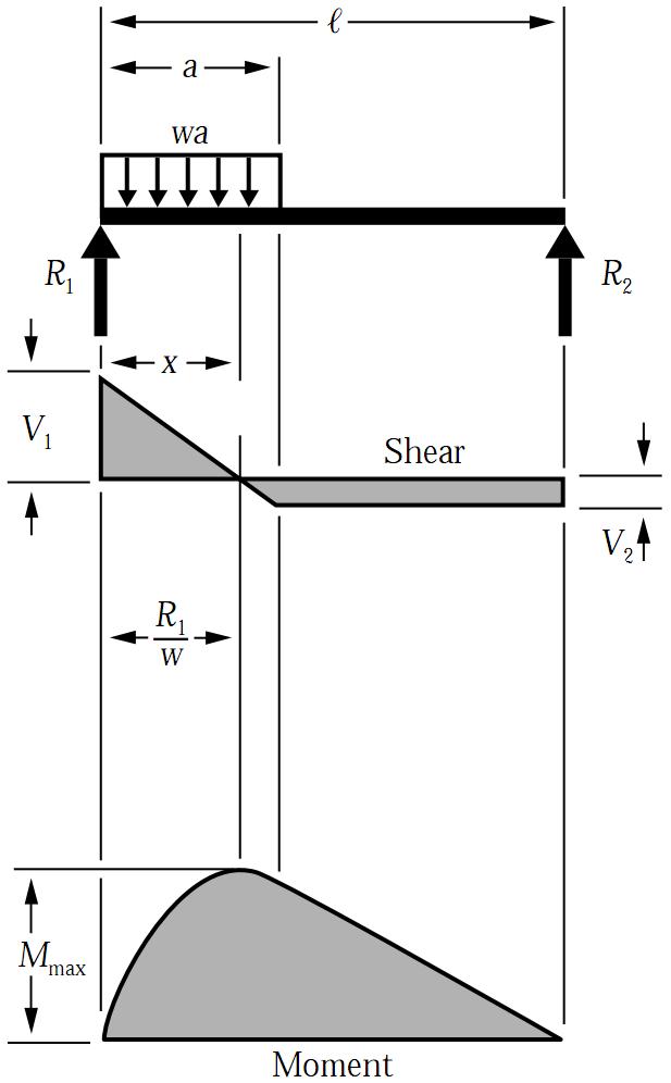
Web the simply supported beam in fig. Web beam guru.com is a online calculator that generates bending moment diagrams (bmd) and shear force diagrams (sfd), axial force diagrams (afd) for any statically determinate (most simply.
Civil and Structural Engineering Boloram Chandra Simple Supported
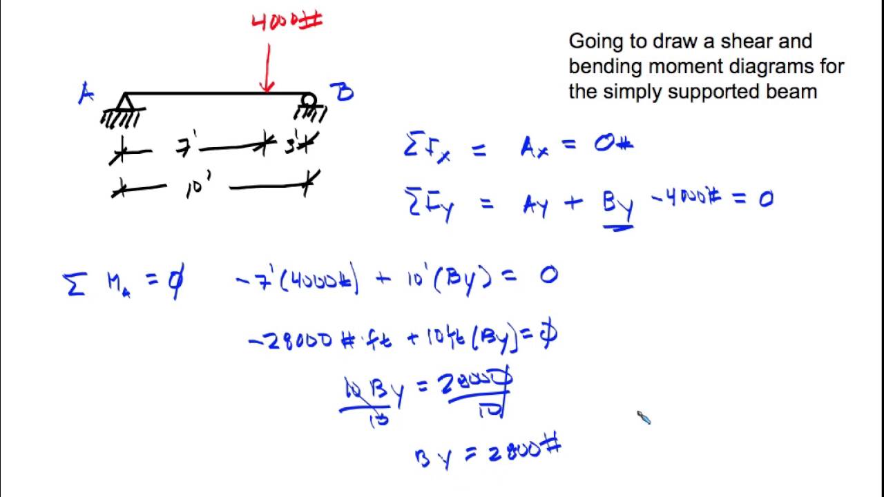
Consider the left or the right portion of the section. Web draw the shear and moment diagrams for the simply supported beam this problem has been solved! The reactions at the supports are found from.
Simply Supported UDL Beam Formulas Bending Moment Equations
You'll get a detailed solution from a subject matter expert that helps you learn core concepts. View the full answer step 2 unlock answer unlock previous question next question not the question you’re looking for?.
Shear and Moment Diagram Simply Supported Beam (Point Load) YouTube
Web steps to draw shear force and bending moment diagrams. (a) is loaded by the clockwise couple c 0 at b. Web let the shear force and bending moment at a section located at a.
SHEAR FORCE AND BENDING MOMENT DIAGRAM FOR SIMPLY SUPPORTED BEAM WITH
(see above) sum up the forces in the vertical direction. Web shear force diagram bending moment. View the full answer step 2 unlock answer unlock previous question next question not the question you’re looking for?.
SHEAR FORCE BENDING MOMENT OF A SIMPLY SUPPORTED BEAM CIVIL ENGINEERING
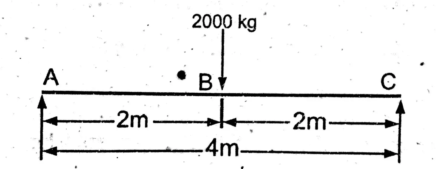
Bending moment at point b = m (b) = 1000 x. And it will be maximum where shear force is zero. Web steps to draw shear force and bending moment diagrams. In sfd and bmd.
Simply Supported UDL Beam Formulas Bending Moment Equations
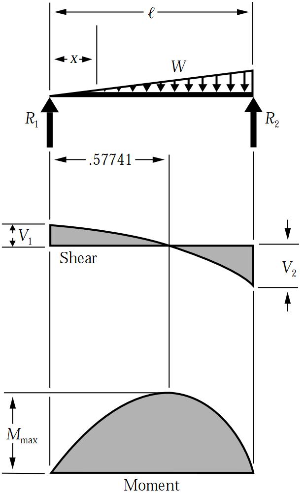
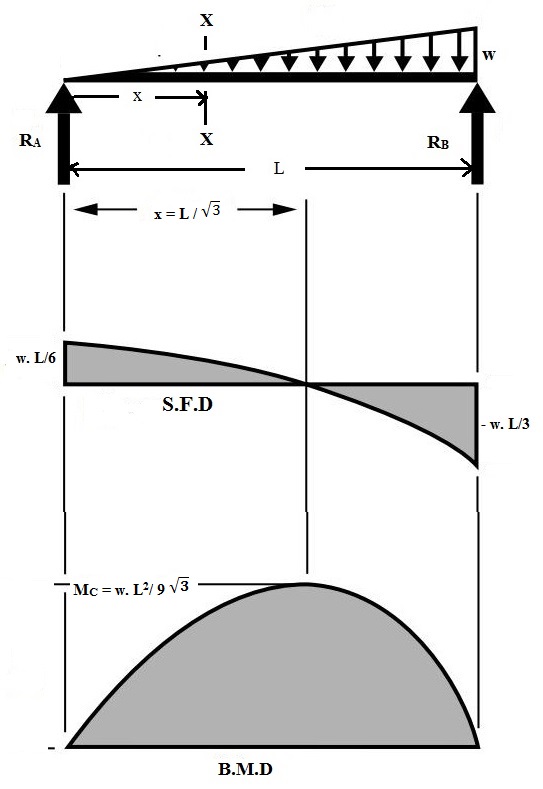
Web civil engineering civil engineering questions and answers for the simply supported beam supporting a trapezoidal distributed load given below, draw shear and moment diagrams and determine the maximum absolute value of both the shear.

Draw shear force and bending moment diagrams for a simply supported
Bending moment m ( x) = 1 / 2 ⋅ q ⋅ x ⋅ ( l − x) max bending moment m m a x = 1 / 8 ⋅ q ⋅ l 2 shear.

Shear force and bending moment diagrams for a simply supported beam
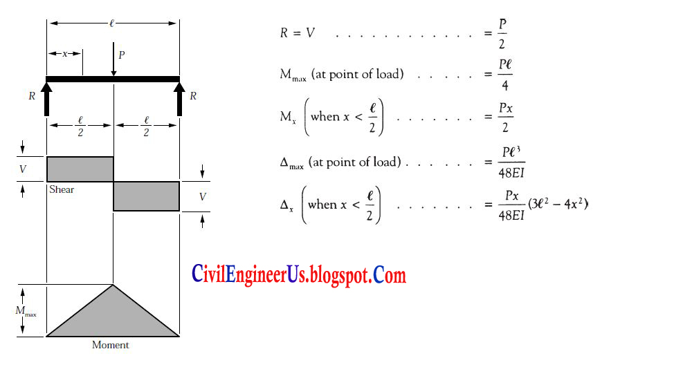
Point load shear force distribution. In case of simply supported beam, bending moment will be zero at supports. Neglect the weight of the beam. Web shear and moment diagrams consider a simple beam shown of.
Draw The Shear And Moment Diagrams For The Simply-Supported Beam Point load shear force distribution. Web there are 2 steps to solve this one. The support reactions a and c have been computed, and their values are shown in fig. Draw the shear and moment diagrams for the simply supported beam. Web civil engineering civil engineering questions and answers for the simply supported beam supporting a trapezoidal distributed load given below, draw shear and moment diagrams and determine the maximum absolute value of both the shear force, v.