Drawing Chamfer Callout
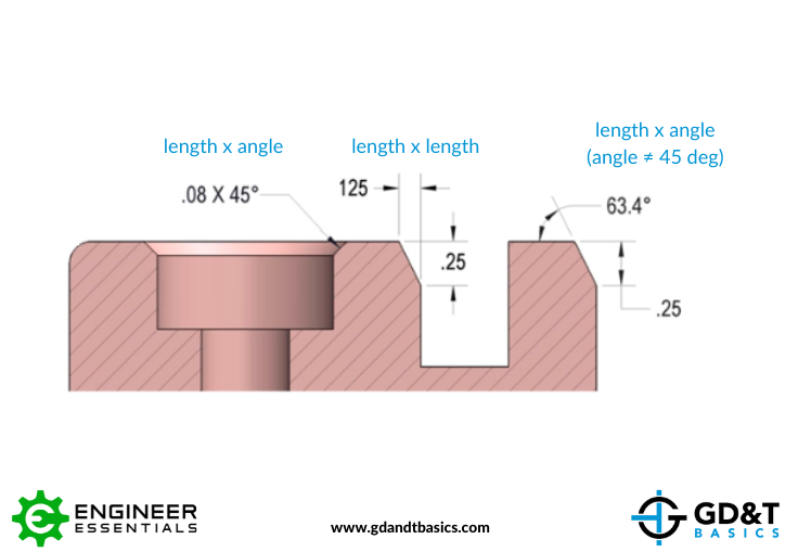
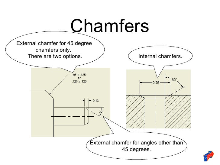
Drawing Chamfer Callout - Web dimensioning chamfers is done with a call out that specifies the length of the chamfer along with the angle of the chamfer. X display is the size of the x in a chamfer dimension with two numbers, such as 1 x 45° (length x angle), 45° x 1 (angle x length), 1 x 1 (length x length) or. Web you can dimension chamfers in drawings. The feature being referenced is indicated through the use of a leader line. Web start with our guide to blueprints and learn all the basic elements of engineering drawings including symbols, terminology and lots of examples.
After drawing the part, from the menu bar select design > solid > modify > chamfer. Drag to place the callout. You just need to give the length of one edge and the corresponding angle to it. Dimensions are required for points, lines, and surfaces that are related functionally or control relationship of other features. Is it customary to use a dash? Web you can dimension chamfers in drawings. Web if the chamfer is only part way around the cylinder, then more information is needed, such as where does it begin or end.
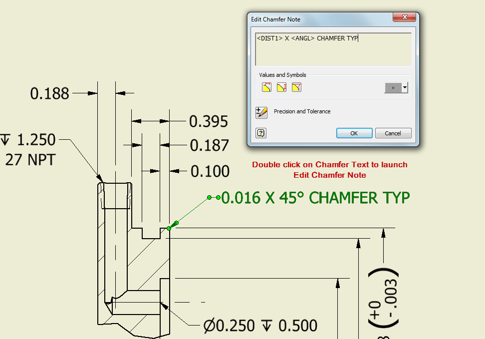
Inventor Chamfer 메모에서 통화의 소수 자릿수를 변경할 수있는 기능 Inventor 제품 Autodesk
In addition to the usual dimension display properties, chamfer dimensions have their own options for leader display, text display, and x display. Then select the edges, features, or faces to chamfer. .040 x 30) to.

Dimensioning Chamfers YouTube
In addition to the usual dimension display properties, chamfer dimensions have their own options for leader display, text display, and x display. Y14.5 clearly says a note 1 x 1 or 1 x 45° is.

Drawing Dimension chamfer note tool Autodesk Community
Types, dimensions & callout this guide will help you to understand what is a chamfer and point out some differences. Web local notes, also referred to as callouts, are included on a drawing to specify.
Solved Multiple chamfers on drawings PTC Community
A break edge means the removal of material, usually in the form of a chamfer or radius to remove the sharp edge. You just need to give the length of one edge and the corresponding.
Chamfer Dimensioning GD&T Basics
Is it to call out the note with a leader (.25 x 45°) or to add two seperate dimensions (one linear and chamfer callout? X display is the size of the x in a chamfer.

Introduction to AutoCAD Chamfer YouTube
A break edge means the removal of material, usually in the form of a chamfer or radius to remove the sharp edge. Is it customary to use a dash? Web solidworks course for beginners: Is.

Adding a Chamfer Dimension YouTube
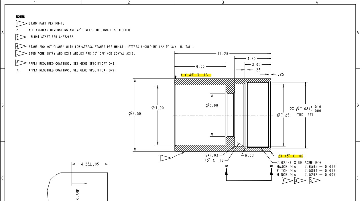
Web you can dimension chamfers in drawings. Web if the chamfer is only part way around the cylinder, then more information is needed, such as where does it begin or end. Web a convenient guide.
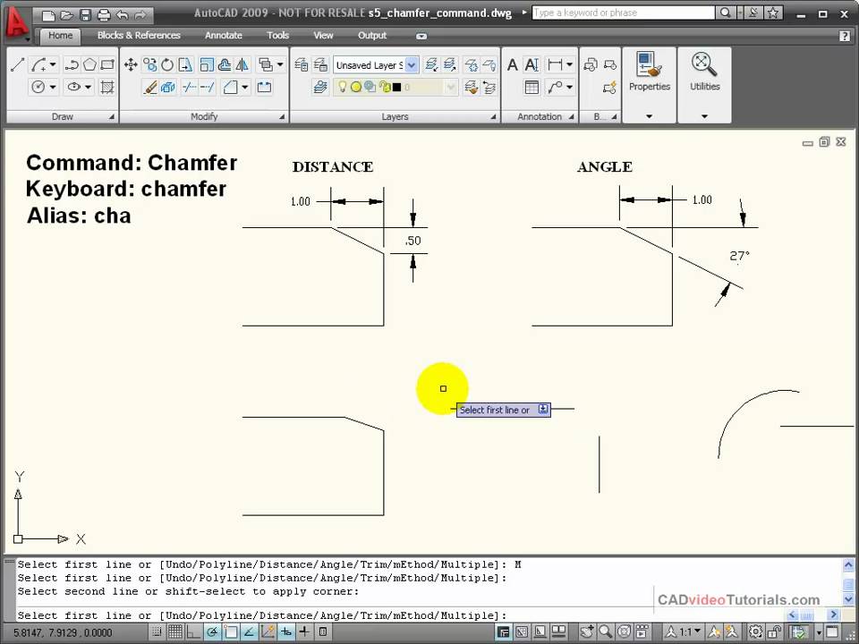
AutoCAD Tutorial Using the CHAMFER Command YouTube
Web introduction dimensioning refers to the addition of size values to drawing entities. Drag to place the callout. Chamfers can also be specified. Web you can dimension chamfers in drawings. Web a convenient guide for.

Solved 2D drawing chamfer dimmension type PTC Community
Web start with our guide to blueprints and learn all the basic elements of engineering drawings including symbols, terminology and lots of examples. Basic dimensioning is the addition of only functional size values to drawing.
Dimensioning standards
Then select the edges, features, or faces to chamfer. If no angle is given the chamfer is assumed to be at 45 degrees. X display is the size of the x in a chamfer dimension.
Drawing Chamfer Callout You just need to give the length of one edge and the corresponding angle to it. Select a circle that is part of a hole feature, or a thread that is part of an external thread feature. The feature being referenced is indicated through the use of a leader line. If you created the chamfer using the chamfer feature, simply show your dimensions for that feature or view. Solidwork has a dimension style that is c1 for 45 degree chamfers.