Engineering Drawing Symbols List
Engineering Drawing Symbols List - 1.7 identify the symbols used on engineering p&ids for the following types of instrument signal controllers and modifiers: Note the comparison with the iso standards. There are many different standards related to technical drawings. Web 18.06.2020 by andreas velling engineering drawing basics explained an engineering drawing is a subcategory of technical drawings. Geometric tolerances are specified using symbols on a drawing.
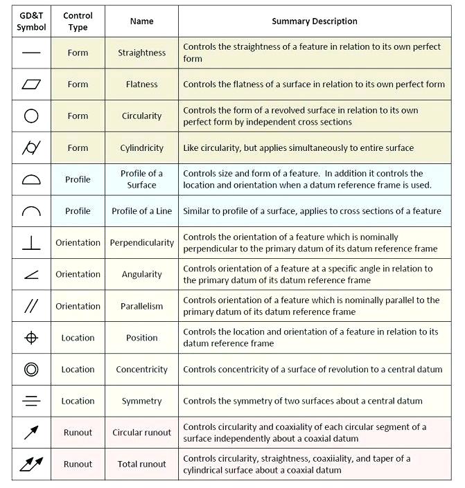
The purpose is to convey all the information necessary for manufacturing a product or a part. You can use this guide as a reference to help you decipher what is written on your engineering drawing. Web they are a standard set of symbols used for the identification of measurements and functionality within the process. Currently, we have 16 symbols for geometric tolerances, which are categorized according to the tolerance they specify. Web 1 clarity and conciseness engineering drawings often contain a large amount of information, including dimensions, tolerances, annotations, and other details. Web there are numerous abbreviations and symbols in various engineering drawing categories. Concentricity is a very complex feature because it relies on measurements from derived median points as opposed to a surface or feature’s axis.

How To Read Architectural Drawings Symbols The Architect
Architect's scale and engineer's scale; Web every civil engineering firm uses custom plan symbols in their drawings so it is important to check the drawing legend. Using abbreviations and symbols allows for concise representation, making.

Engineering Drawing Symbols And Their Meanings Pdf at PaintingValley
Learners examine the drawing symbols used for counterbore, countersink, spotface, radius, diameter, and depth. Web they are a standard set of symbols used for the identification of measurements and functionality within the process. Note the.

Civil Engineering Drawing Symbols And Their Meanings at PaintingValley
The purpose is to convey all the information necessary for manufacturing a product or a part. Bolts and screws are commonly used to hold components together. Web what are some examples of symbols used to.

Engineering Drawing Symbols And Their Meanings Pdf at PaintingValley
You can also check out the gd&t symbols and terms on our site. Geometric tolerances are specified using symbols on a drawing. The symbols below come from the us national cad standard or are typical.

ANSI Standard JSTD710 Architectural Drawing Symbols Bedrock Learning
Using abbreviations and symbols allows for concise representation, making the drawings easier to read and understand. The purpose is to convey all the information necessary for manufacturing a product or a part. The symbols below.

Types of Engineering Drawing Symbols and Uses इंजीनियरिंग ड्राइंग के
Web gd&t drawings and symbols. Also check gd & t symbols and terms here. To provide detail about the components, a 5 letter system is used: Basic types of symbols used in engineering drawings are.
Mechanical Engineering Symbols Cadbull
Web this list includes abbreviations common to the vocabulary of people who work with engineering. There are many different standards related to technical drawings. You can also check out the gd&t symbols and terms on.

Engineering Drawing Symbols And Their Meanings Pdf at PaintingValley
Web every civil engineering firm uses custom plan symbols in their drawings so it is important to check the drawing legend. This list includes abbreviations common to the vocabulary of people who work with engineering.
Machining Symbols In Drawing Pdf
Web they are a standard set of symbols used for the identification of measurements and functionality within the process. In the quiz that completes the activity, they associate these symbols with machining applications. Web 18.06.2020.

Mechanical Engineering Drawing Symbols Pdf Free Download at
The following are commonly used engineering drawing symbols and design elements. Basic types of symbols used in engineering drawings are countersink, counterbore, spotface, depth, radius, and diameter. Web examples of the organizations that establish standards.
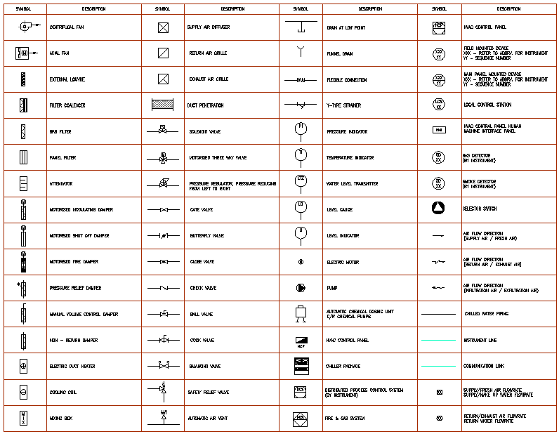
Engineering Drawing Symbols List The following are commonly used engineering drawing symbols and design elements. Web there are numerous abbreviations and symbols in various engineering drawing categories. Iso , aisi, sae, astm, asme, ansi, din. The basic symbol types used in engineering drawings are diameter, depth, radius, counterbore, spotface, and countersink. To provide detail about the components, a 5 letter system is used: