Grease Trap Drawings Design
Grease Trap Drawings Design - Start your next project today! Web in this blog post, we will discuss the importance of grease trap design, its key components, and the benefits of professional grease trap drawings. Grease traps are designed to intercept and separate fats, oils, and grease (fog) from wastewater, preventing fog buildup in sewer lines. Calculate the capacity of the fixture (ex: Web grease trap sizing chart;
Next, multiply all three values. Capacity of the sink) your grease trap is servicing by measuring the length, width, and depth. Web a grease trap is a receptacle that kitchen waste water flows through before entering the sanitary sewer lines. Grease traps should be strategically placed close to the source of fog discharge, such as sinks. Web grease trap design drawings offer a fascinating glimpse into the intricate world of plumbing infrastructure. Web the minimum requirements for grease trap design are: Cad drawings for grease traps;

Grease Trap Pit CAD Block And Typical Drawing For Designers
Low boy plastic grease trap; This receptacle captures, or traps grease.the industry term for animal fats and vegetable oils, is 10 to 15% less dense, or lighter than water. Web a grease trap is a.

Kitchen Grease Trap Design Drawings Design Talk
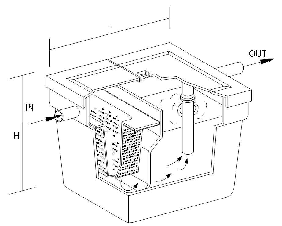
The outlet pipe has a tee that allows the internal discharge to be located within. Number of meals served at peak operating hour (seating capacity) x peak factor where peak factor for fast food restaurant.

Grease Trap Above and Below Ground Viking Plastics
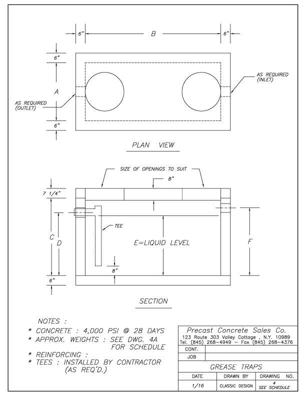
Because of this, a manual grease trap can easily be installed under most commercial sinks. Web typical grease trap connections s s scale: Web grease trap sizing chart; A grease trap should be able to.
Grease trap design in AutoCAD 2D drawing, CAD file, dwg file Cadbull
These meticulously crafted illustrations showcase Next, multiply all three values. Web design standard grease trap & interceptors part 1 general 1.01 installation of a grease trap / interceptor is required at all commercial, institutional, and.
Grease Trap Design Drawings Grease Trap Dwg Detail For Autocad
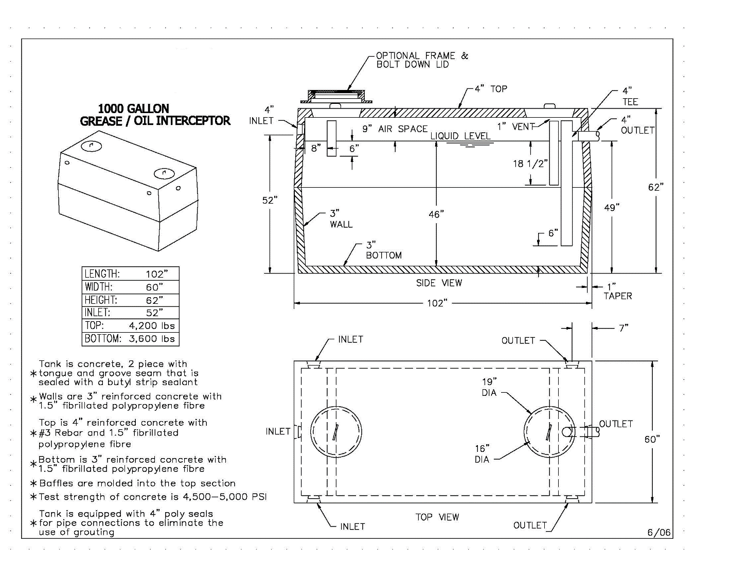
42.08 x 0.75 = 31.56 usg. Web cad drawings for grease traps: Low boy plastic grease trap; A grease trap should be able to hold all the kitchen wastewater entering it during times of maximum.

Grease Trap Design Drawings Design Talk
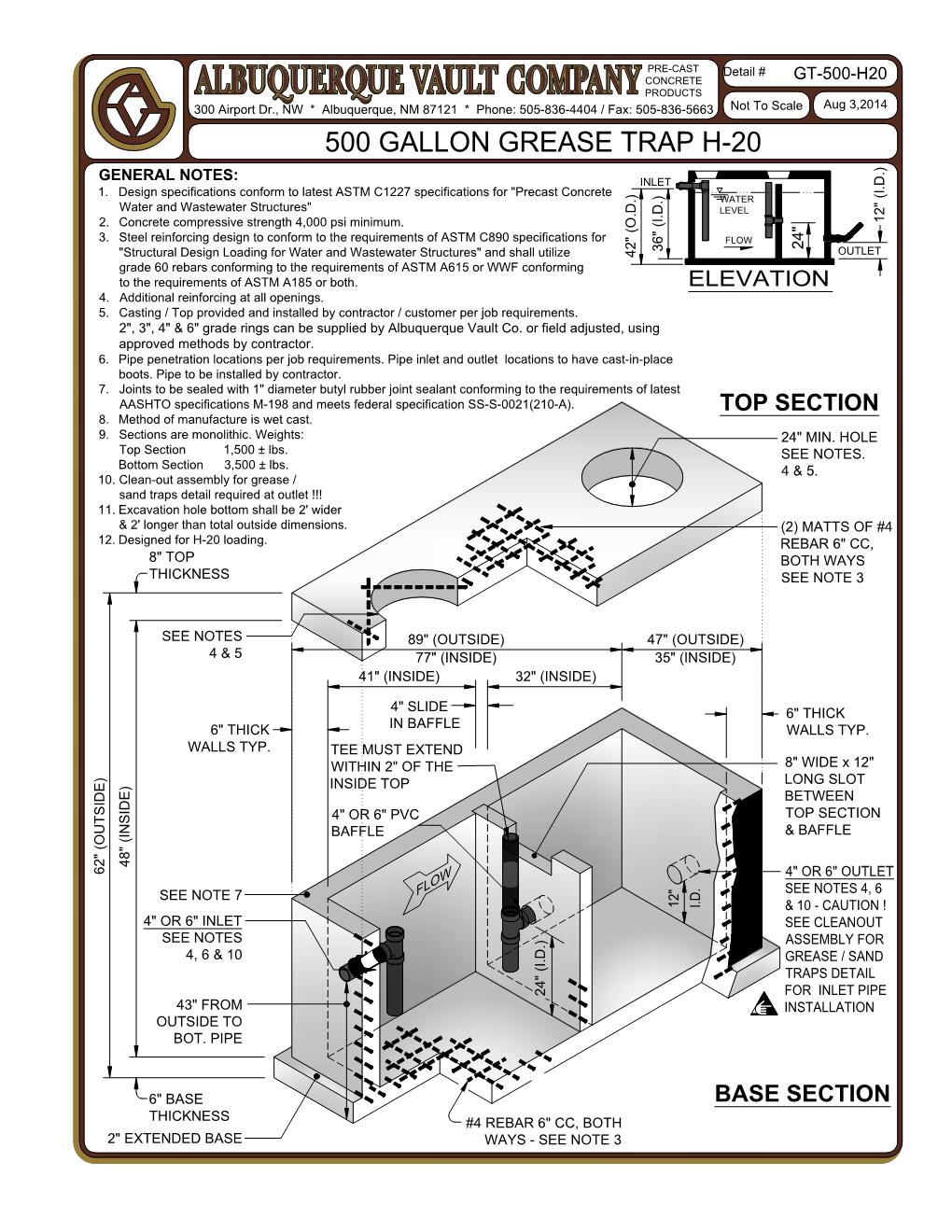
25 gpm grease trap low profile cad drawings file. Web grease trap sizing chart; Web the minimum requirements for grease trap design are: A control manhole over each compartment for inspection and monitoring purposes We.
Detail Grease Trap Design Drawings
Use inches for the capacity of the sink. Uniform plumbing code, appendix h number of meals per peak hour (1) x waste flow x rate (2) retention time (3) x storage factor (4) = size.

Detail Grease Trap Design Drawings
Next, multiply all three values. Web grease trap design drawings offer a fascinating glimpse into the intricate world of plumbing infrastructure. Larger establishments require bigger traps to accommodate higher flow rates. A control manhole over.
Grease Trap Design Drawings Design Talk
The size of the grease trap depends on the volume of wastewater generated and the fog content. Number of meals served at peak operating hour (seating capacity) x peak factor where peak factor for fast.

Grease Trap Design Drawings Design Talk
Web typical grease trap connections s s scale: 42.08 x 0.75 = 31.56 usg. Start your next project today! Web grease trap design drawings offer a fascinating glimpse into the intricate world of plumbing infrastructure..
Grease Trap Drawings Design Number of meals served at peak operating hour (seating capacity) x peak factor where peak factor for fast food restaurant is.1.33 Because of this, a manual grease trap can easily be installed under most commercial sinks. Grease traps should be strategically placed close to the source of fog discharge, such as sinks. 15 gpm cad drawings zip file. Web grease trap design drawings offer a fascinating glimpse into the intricate world of plumbing infrastructure.