Grid Reference In Engineering Drawing
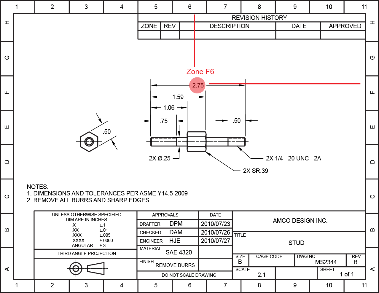
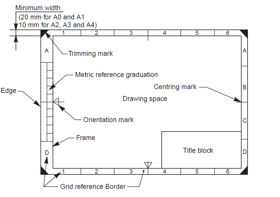
Grid Reference In Engineering Drawing - Web the typical ‘engineering’ style drawing border has a grid reference frame drawn into the border. Web the grid references are used to the location and teamwork of item. The grid lines themselves are drawn with a 0.35mm line weight. + read more engineering drawing frame border. Reference grid serves for better orientation in large drawings.
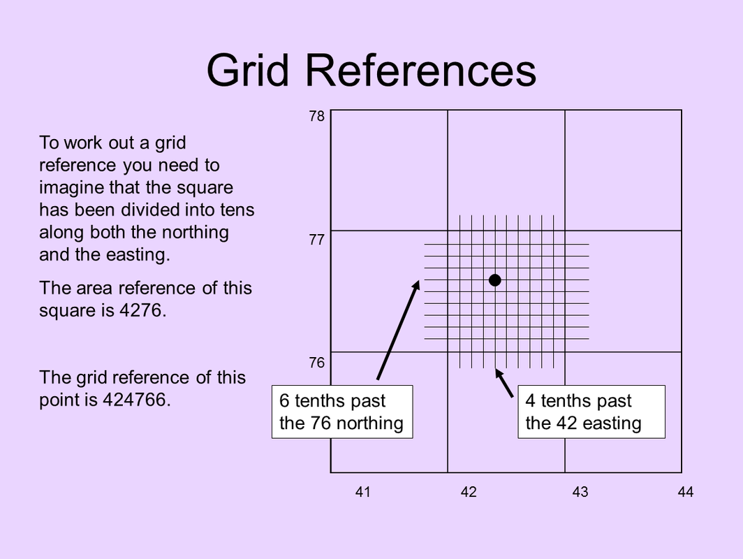
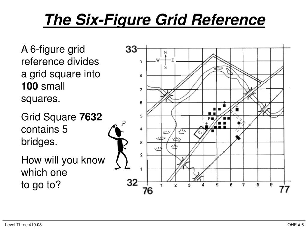
Web asme y14.24, “drawings types and applications of engineering drawings”, was adopted on. + read more engineering drawing frame border. A common use is to specify the geometry necessary for the construction of a component and is called a detail drawing. The grid lines themselves are drawn with a 0.35mm line weight. Web dec 13, 2004 #1 m maxweston new member g'day from perth aust i was asked the other day about grid referencing on drawingsand although i have a alfa/numeric grid on all of my formats and reference details to relevent coordinates, i do this manually. Web to help locate a specific point on a referenced print, most drawings, especially piping and instrument drawings (p&id) and electrical schematic drawings, have a grid system. Reference grid serves for better orientation in large drawings.
Area and Grid Reference HSIE Teachers Skills
For example, you will use your floor plan to show the reader the points at which you will take an elevation, or a section line through the building. They provide reference points which helps the.
PPT Principles of a Grid Reference PowerPoint Presentation, free
Web reference markers are labels on a drawing that indicated where the drawing is taken from and what it is showing. Web engineering drawings are the medium through which engineers communicate the design requirements of.
Introduction to Engineering Drawings
Web the typical ‘engineering’ style drawing border has a grid reference frame drawn into the border. You are spaced 50mm alone from which centring cable. The grid lines themselves are drawn with a 0.35mm line.
A beginners guide to grid references OS GetOutside
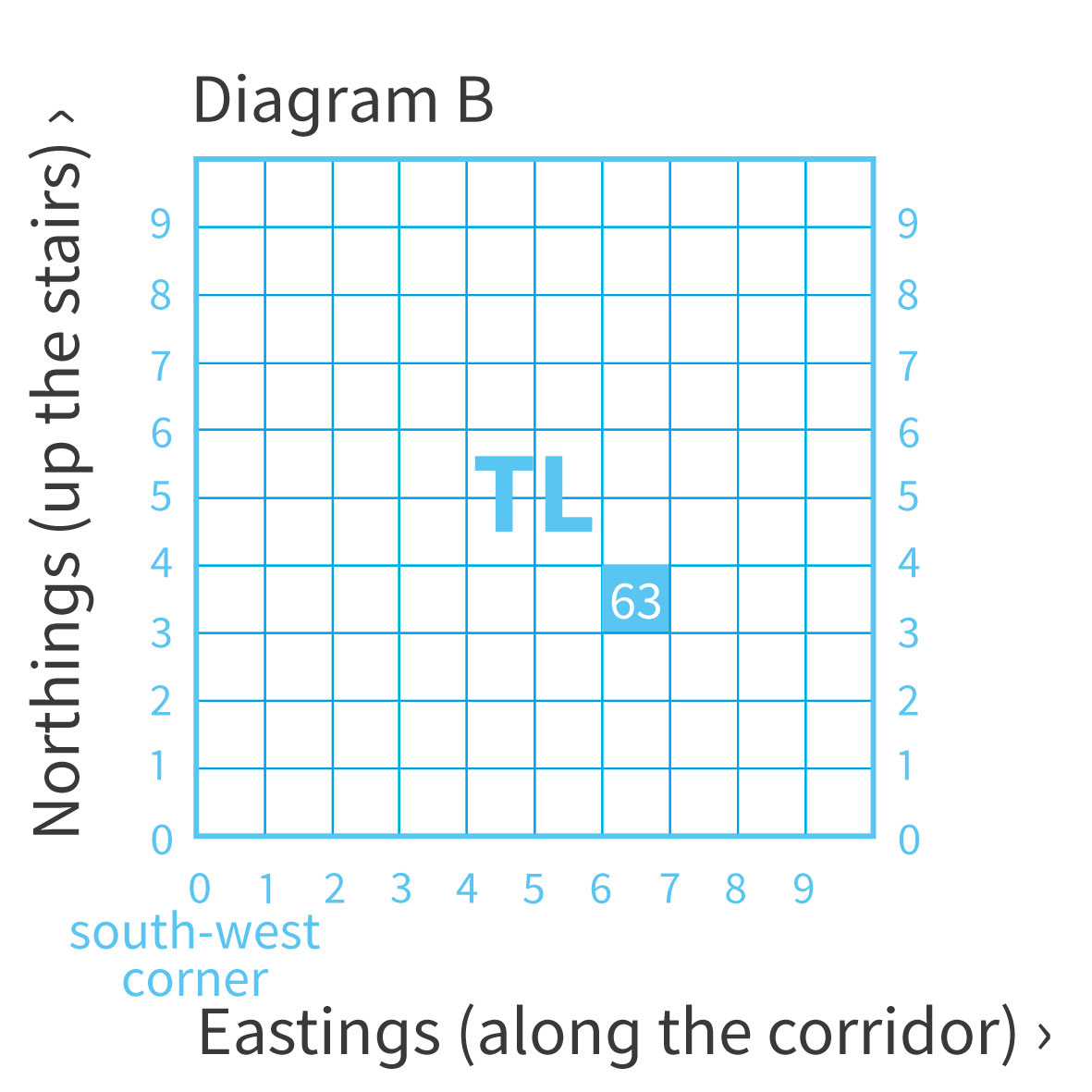
+ read more technical drawing standards: Web the typical ‘engineering’ style drawing border has a grid reference frame drawn into the border. Web zoning, a drawing may be divided up into a grid using letters.
Grid Lines and drawing Axis How to setup for AutoCAD Drawing Standard
The mesh lines themselves are drawn with a 0.35mm pipe weight. They are spaced 50mm apart from the centring lines. They are spaced 50mm apart von to centring lines. Zoning is usually used for large.

Layout of Drawing SheetEngineering Drawingइंजीनियरिंग ड्राइंग शीट
These consist of elevation markers, section markers and detail markers. Web the typical ‘engineering’ type drawing bordered has a grid reference frame drawn into which borderline. Proposed changes by dod activities must be submitted to.

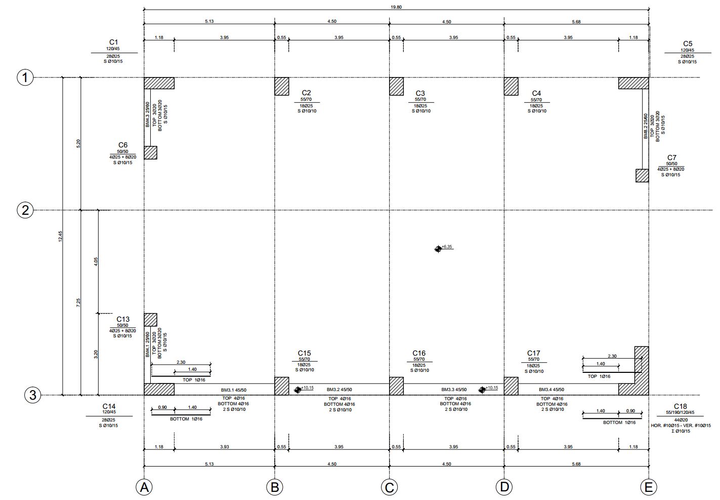
How Do You Read Column Drawings 2021?
The last two divisions bucket be whatever size they end top. The newest two divisions can be whatever product they end skyward. Web to help locate a specific point on a referenced print, most drawings,.
ENGINEERING DRAWINGLayout of Drawing Sheets
+ read more engineering drawing frame border. Web engineering symbology, prints, & drawings intro to print reading 2 anatomy of a drawing a generic engineering drawing can be divided into the following five major areas.

Grid Reference on Structural Drawings YouTube
Web engineering drawings are the medium through which engineers communicate the design requirements of an engineered product or component. They are spaced 50mm apart from the centring lines. Number of divisions for a particular sheet.

Grid Lines and Axis for CAD Drawings St5 CAD Standard
Web find out how to draw an engineering style grid reference frame on your technical drawings. Proposed changes by dod activities must be submitted to the dod adopting activity: One grid lines themselves are drawn.
Grid Reference In Engineering Drawing The grid references are used for the location and coordination of details. 14 february 2000 for use by the department of defense (dod). Web reference markers are labels on a drawing that indicated where the drawing is taken from and what it is showing. Web to help locate a specific point on a referenced print, most drawings, especially piping and instrument drawings (p&id) and electrical schematic drawings, have a grid system. Is there a way of making the grid inteligent?