How To Draw A Pv Diagram
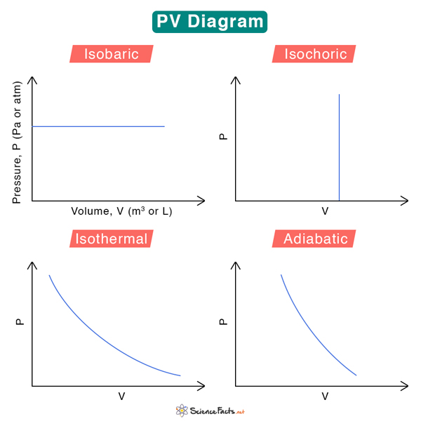
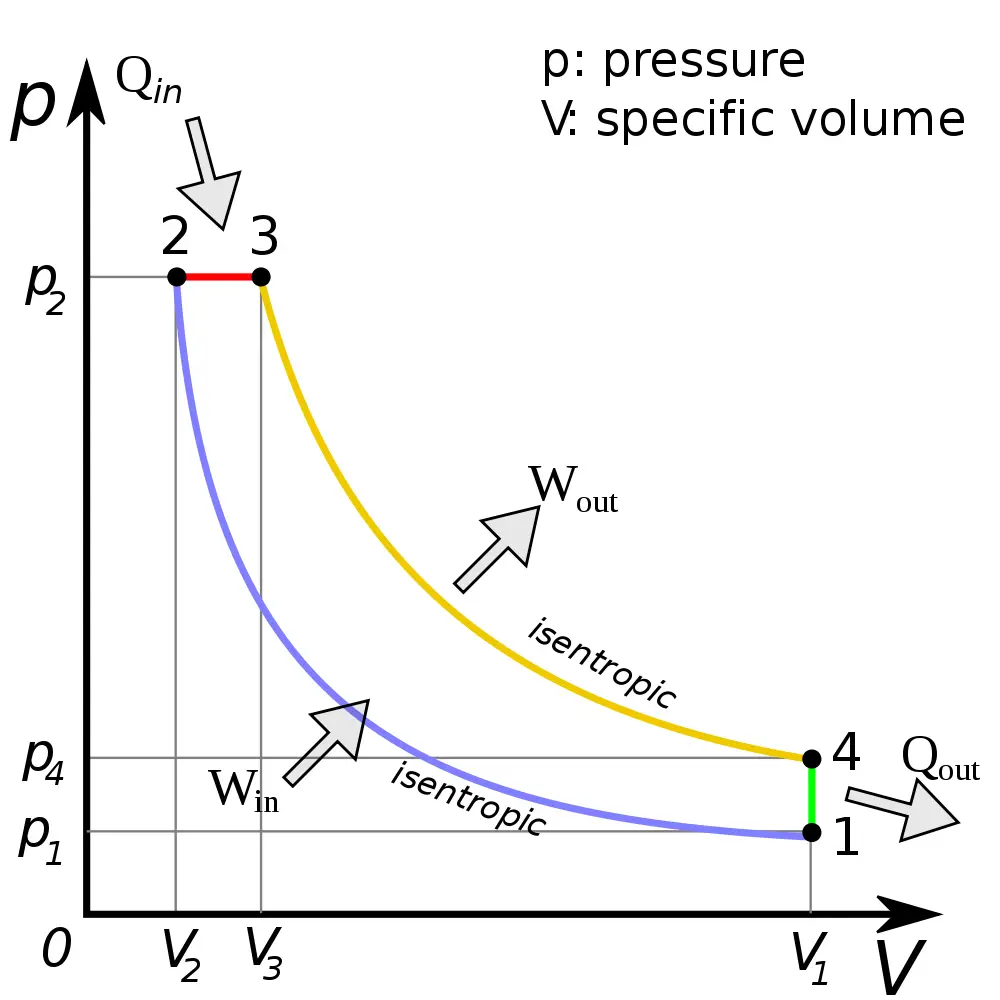
How To Draw A Pv Diagram - A pencil was used to draw the diagram. Heat q = ∆ u + w = nc ∆ t curves isobaric constant pressure bar comes from the greek word for heavy: Let’s see what’s happening in the cylinder during each piston stroke, how the pressure and volume are changing inside the cylinder. Identify the processes in the cycle, identify useful relationships between the variables, look for keywords that give you useful information, calculate any variable that you need, order your data, and then draw the cycle. Web pv diagrams clearly illustrate that the work done depends on the path taken and not just the endpoints.
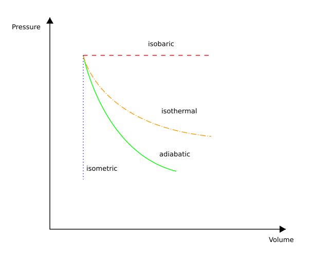
A pencil was used to draw the diagram. Pv diagram for pure systems. A gas undergoes two processes. Web 43k views 5 years ago. Let’s see what’s happening in the cylinder during each piston stroke, how the pressure and volume are changing inside the cylinder. You can also sketch a pressure vs. There are three types of thermodynamic processes you should know:
PV Diagram Definition, Examples, and Applications
Web how do you plot a pv diagram? Pv diagram for pure systems. Two moles of an ideal gas are heated at constant pressure from t = 27°c to t = 107°c. Here’s how you.
Draw the PV diagram and the TS diagram for the
Consider a gas sealed in a container with a tightly fitting yet movable piston as seen below. Web the graph in fig. In the first, the volume remains constant at 0.200 m^3 and the pressure.
![[Solved] How to draw this PV graph? 9to5Science](https://i.stack.imgur.com/mvjJ3.png)
[Solved] How to draw this PV graph? 9to5Science
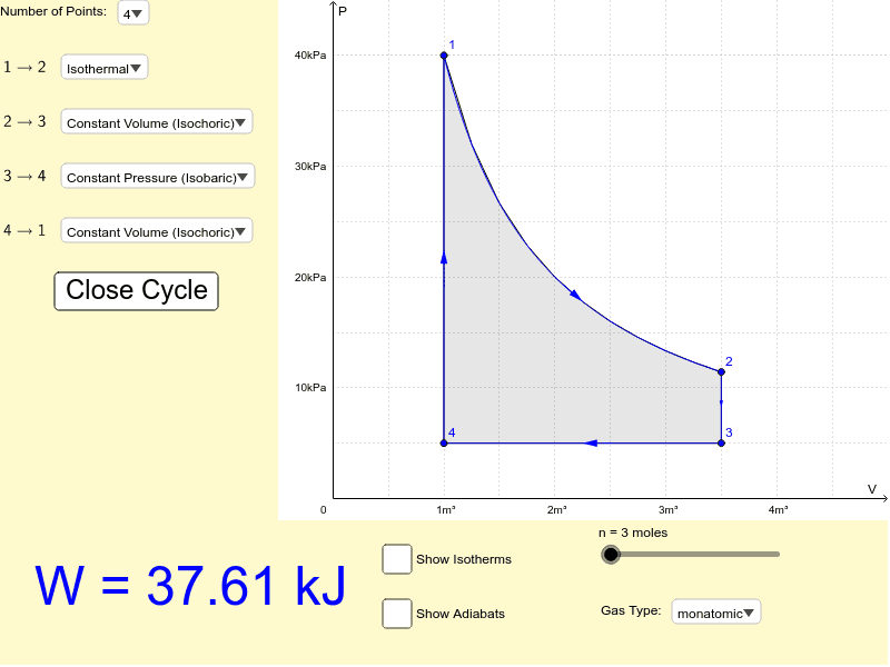
Web instructions this simulation calculates the net work done by a closed cycle. See what happens when the temperature of the ideal gas or the volume is changed (at constant temperature). Weighted piston, flexible container.
PV Diagram and Work GeoGebra
Web how to draw ts diagram from pv diagram. Web how do you plot a pv diagram? Two moles of an ideal gas are heated at constant pressure from t = 27°c to t =.
Understanding the PressureVolume Diagrams — Omnia MFG
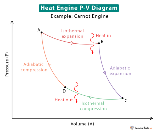
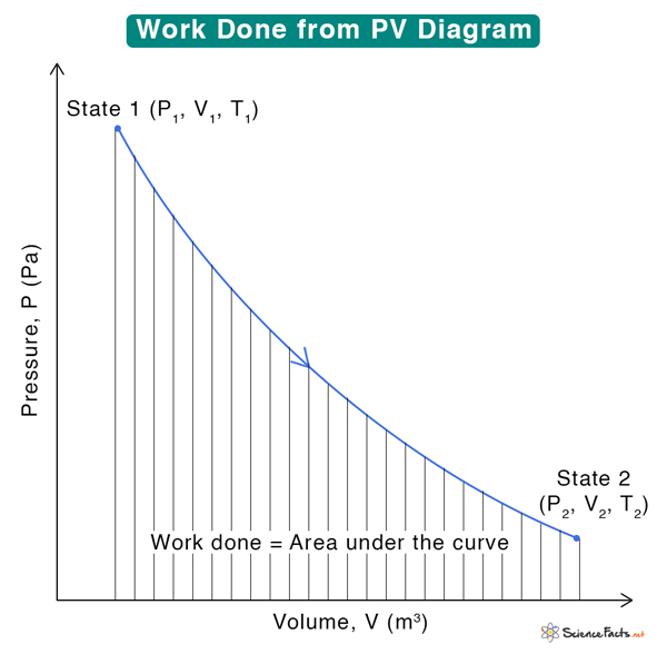
Web pv diagrams clearly illustrate that the work done depends on the path taken and not just the endpoints. Web how to draw pv diagram. Which pv diagram represents the correct process path? Work w.
Pv Diagram Constant Volume
Web instructions this simulation calculates the net work done by a closed cycle. Web pv diagrams clearly illustrate that the work done depends on the path taken and not just the endpoints. Web the graph.

pv* diagram of real nonpolar fluid with its isotherms. Download
If ac system is being designed tha. This path dependence is seen in figure (a) below, where more work is done in going from a to c by the path via point b than by.
Diesel Cycle Process, PV Diagram, Efficiency with Derivation
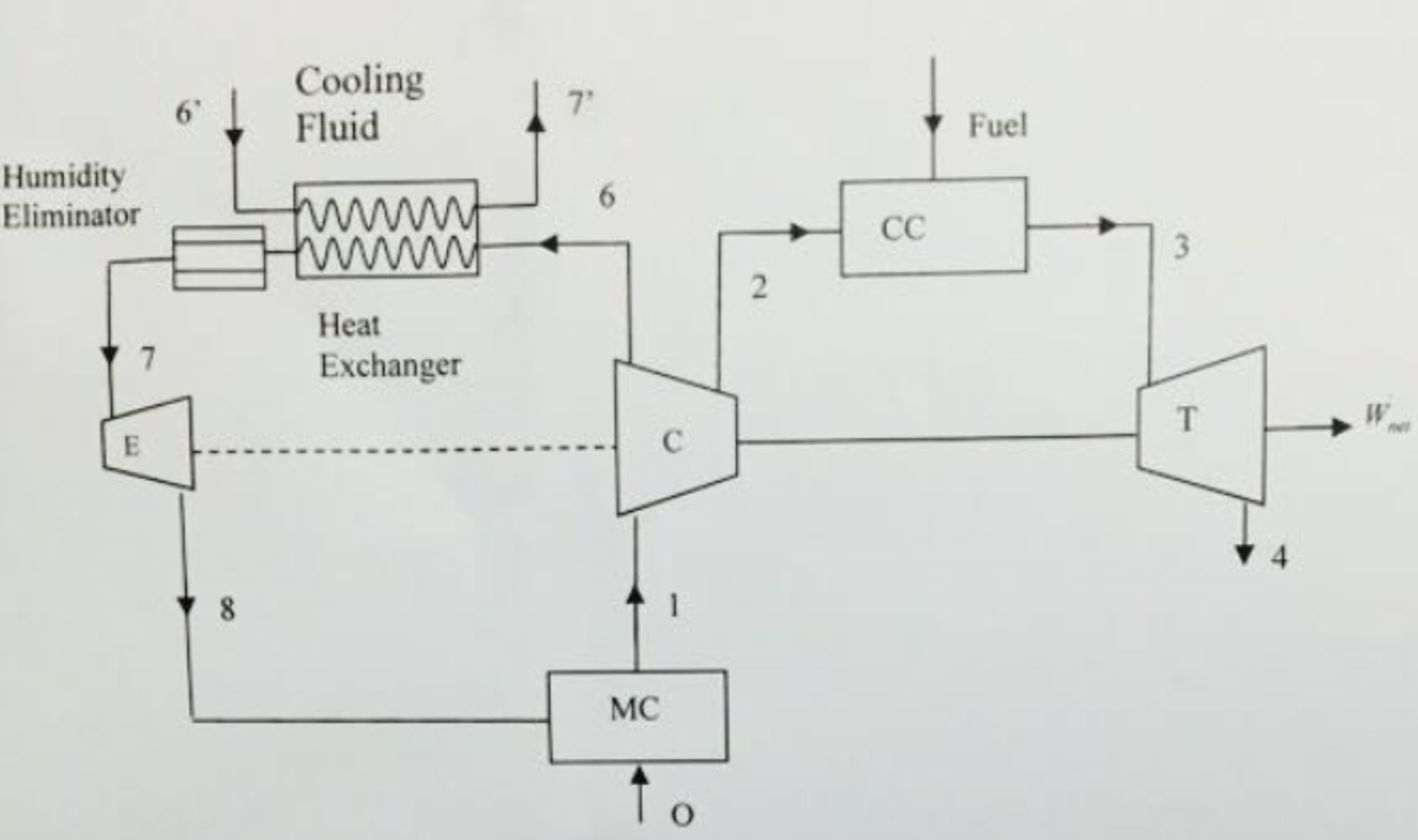
Web draw schematic and single line diagram of solar pv system by zeshanyounis23 fiverr schematic diagrams of solar photovoltaic systems wattuneed schematic diagrams of solar photovoltaic systems wattuneed off grid pv system schematic scientific diagram.
PV Diagram Definition, Examples, and Applications
For example, “the gas pressure doubles”,. Which pv diagram represents the correct process path? Click on close cycle to. A gas undergoes two processes. Consider a gas sealed in a container with a tightly fitting.
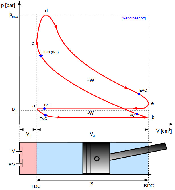
The pressurevolume (pV) diagram and how work is produced in an ICE x
Identify signs that say something about the process. Web thermo drawing t v and p v diagrams. If ac system is being designed tha. An isothermal process is all about keeping the temperature constant, while.
How To Draw A Pv Diagram Volume was traced by a plate moving with the piston, while pressure was traced by a pressure gauge whose indicator moved at right angles to the piston. Select the number of points in the cycle (3 or 4), and then choose which type of process connects each point. Web pv diagrams clearly illustrate that the work done depends on the path taken and not just the endpoints. Web thermo drawing t v and p v diagrams. Such graphs, obtained in clinical practice, are normally somewhat curved, but we have modeled one as a.