How To Draw Bode Plot From Transfer Function
How To Draw Bode Plot From Transfer Function - Web bode plots consist of two individual graphs: %transfer function converted to db phasehrad=atan(w/1). The numerator is an order 0 polynomial, the denominator is order 1. Frequency is the logarithmic axis on both plots. We seek simple intuitive understanding of a transfer function via bode plots vs f.
Web creating bode plots from a transfer function given the transfer function: Draw the overall bode diagram by adding up the results from part 3. How do you plot a bode plot for a given transfer function.if you want to see how to derive a transfer function from a bode. Draw the bode diagram for each part. Web matlab (with the sketched bode plot superimposed on the actual plot) =. Find expressions for magnitude and phase angle and draw the corresponding bode plots. A system’s transfer function is given.

Drawing Bode Plot From Transfer Function ThirdOrder System Real
This is example 2 in this series where we discuss complex poles and required corrections in magnitude. Draw the bode diagram for the transfer function: Find expressions for magnitude and phase angle and draw the.
Bode Plot Matlab How to do Bode Plot Matlab with examples?
Web how to draw bode plots given transfer function (part 1) raiya academy. + 1) 1 this is a stable real pole. Draw the overall bode diagram by adding up the results from part 3..

Drawing Bode Plot From Transfer Function SecondOrder Double Zero
Bode plots using transfer function. In terms of circuits this means we might have a v in v i n and a v out v o u t where our transfer function is h (s).
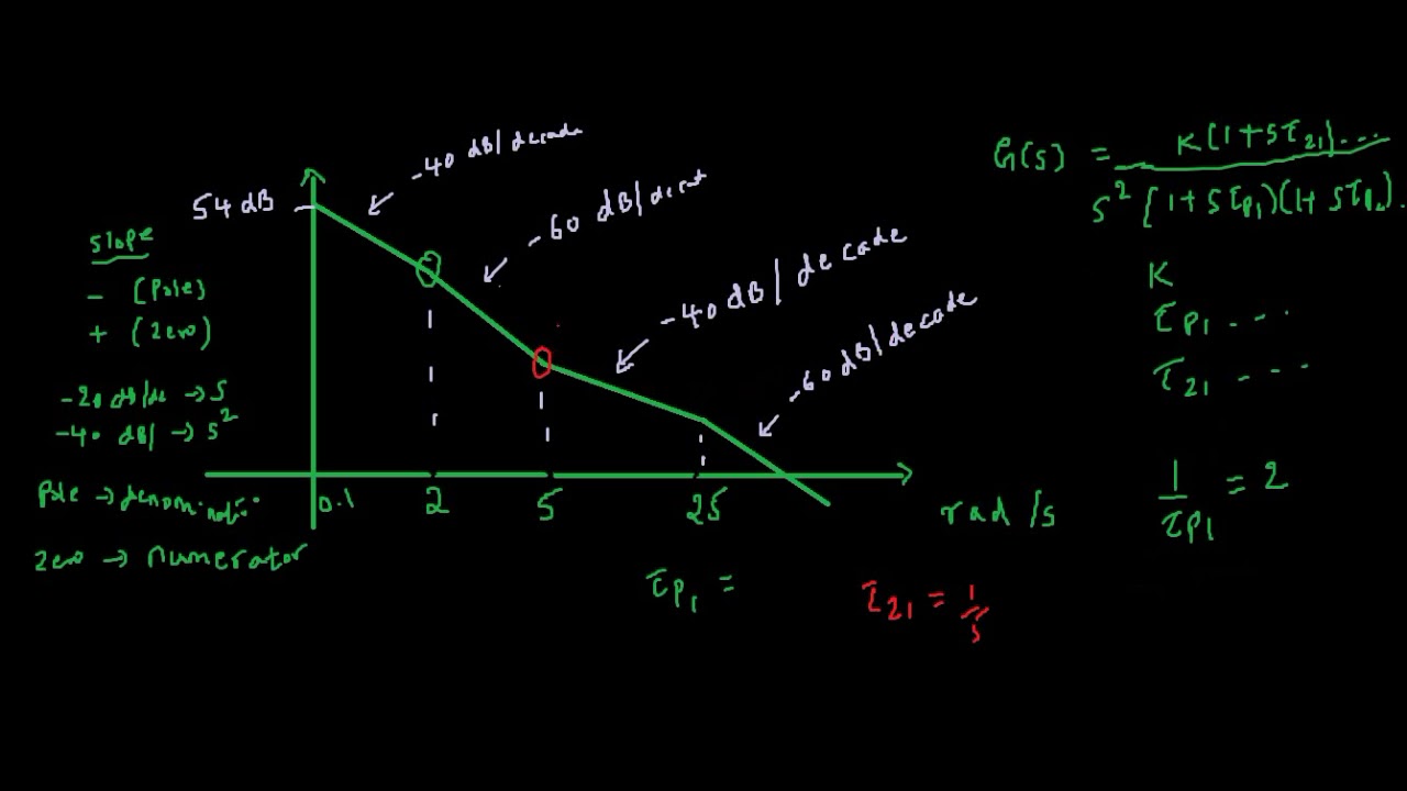
How to find transfer function from Bode Plot YouTube
We will use the asymptotic. This is example 2 in this series where we discuss complex poles and required corrections in magnitude. Determine the zeros and poles of the function: Web the keystone will be.

ME 340 Example Drawing Bode Plot of a Transfer Function 2 YouTube
In terms of circuits this means we might have a v in v i n and a v out v o u t where our transfer function is h (s) = v out v in.

Bode Plot EXAMPLE YouTube
From the open loop response bode plots various design changes may be explored. Web advantage of the scale convention: Web the first part of making a bode plot is finding the magnitude of the transfer.

Deriving the Transfer Function from Bode Plot Example 1 YouTube
Bode plots of transfer functions give the frequency response of a control system to compute the points for a bode plot: So for ω = 2 ω << , i.e., for small values of ω.

How to Derive a Transfer Function Given a Bode Plot (Part 3) YouTube
For both plots, the horizontal axis is either frequency (f) or angular frequency (ω), measured in hz and rad/s respectively. Web we will workout step by step how to convert the transfer function into a.
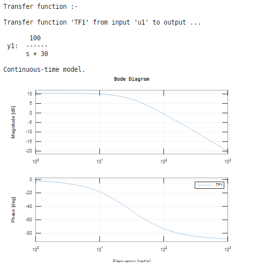
Bode Plot Example Bode Diagram Example MATLAB Electrical Academia
We seek simple intuitive understanding of a transfer function via bode plots vs f. Determine the zeros and poles of the function: = 2 s 1 we convert the transfer function in the following format.
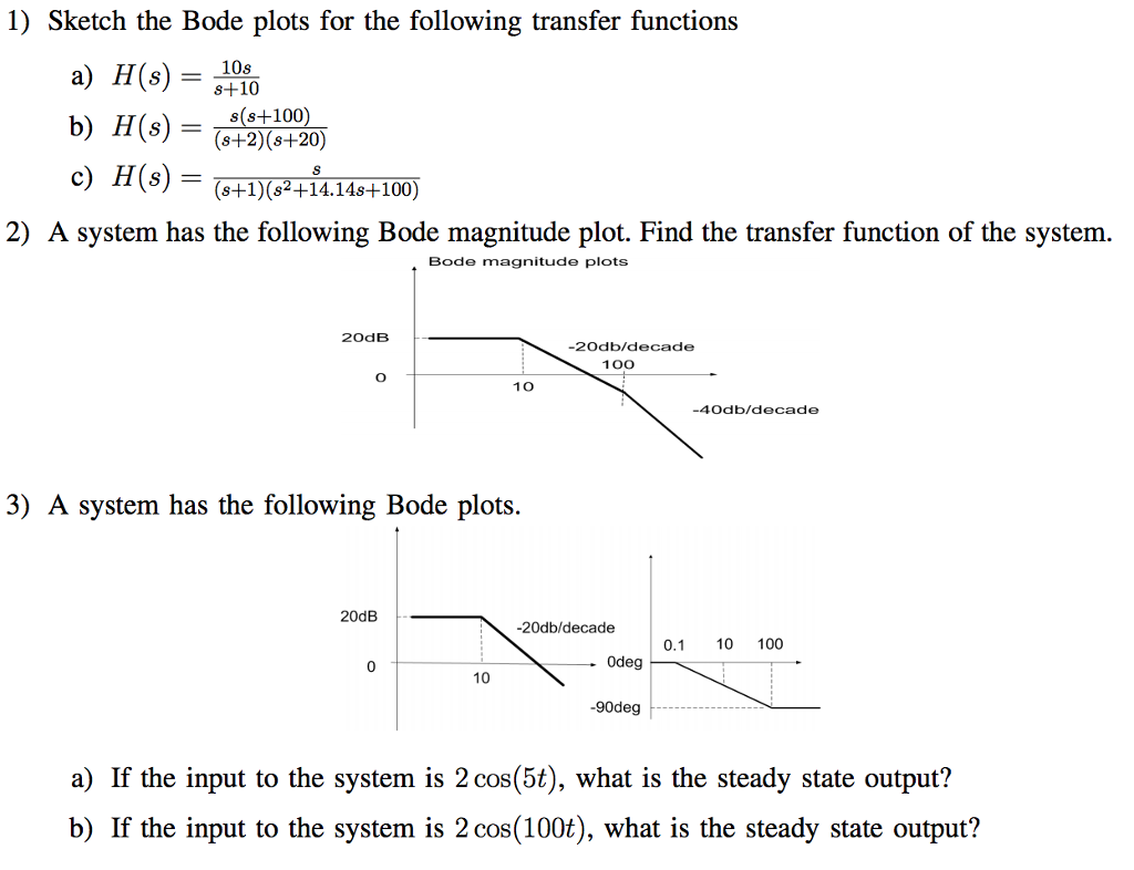
Solved Sketch The Bode Plots For The Following Transfer F...
Click on the transfer function in the table below to. We will workout step by step how to convert the transfer function into a standard form and how to generate. Web we will workout step.
How To Draw Bode Plot From Transfer Function Frequency is the logarithmic axis on both plots. Web example 1 obtain the bode plot of the system given by the transfer function ( s ). From the open loop response bode plots various design changes may be explored. Web the first part of making a bode plot is finding the magnitude of the transfer function. We seek simple intuitive understanding of a transfer function via bode plots vs f.