How To Draw Moment-Curvature Diagram
How To Draw Moment-Curvature Diagram - Determine the range of curvature. Web moment curvature relationships are very important to find out ductility of the structure and the amount of possible redistribution of stresses. Web relation between the radius of curvature, r, beam curvature, κ , and the strains within a beam subjected to a bending moment. Chapter 11, page 2 derivation of the governing equation goal: Notice that \(a\) and \(c\), which are simple supports.
Bending stress varies linearly over beam cross section and is maximum at the. Notice that \(a\) and \(c\), which are simple supports. The rc members were designed as compression controlled members meaning that their failure initiates in the concrete prior to yielding of the steel tension reinforcement. The conjugate beam loaded with the \(\frac{m}{e i}\) diagram is shown in figure 7.17c. Chapter 11, page 2 derivation of the governing equation goal: Determine the range of curvature. Web relation between the radius of curvature, r, beam curvature, κ , and the strains within a beam subjected to a bending moment.
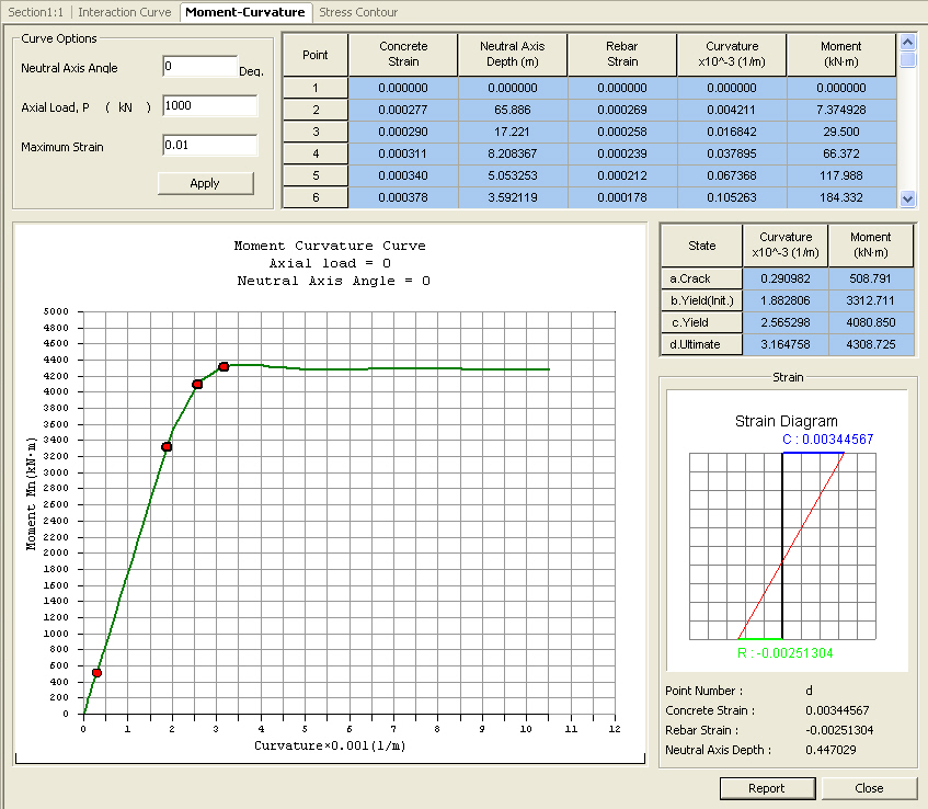
MomentCurvature Curve
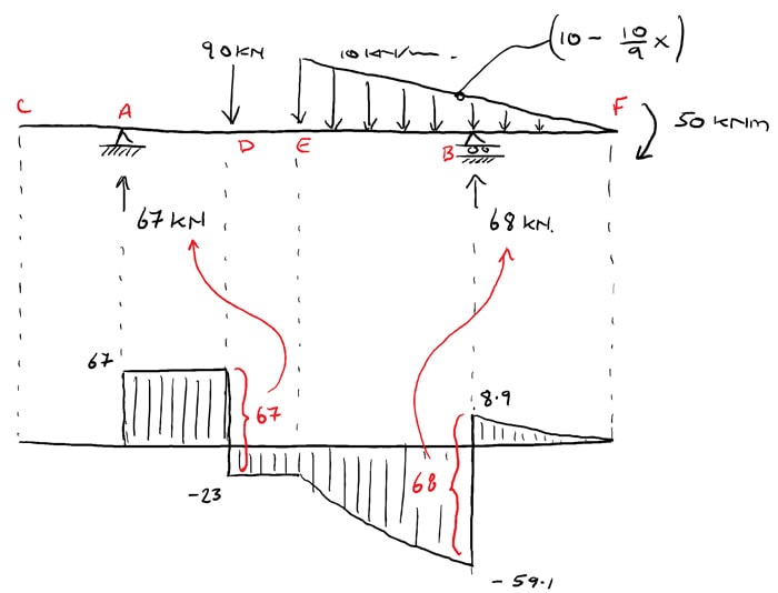
This technique is also applied by cevik et al [11] and chen et al [12]. The maximum value of \(m\) is \(9q_0 l^2/32\), the total area under the \(v\) curve up to this point. (3).

Learn How To Draw Shear Force And Bending Moment Diagrams Engineering
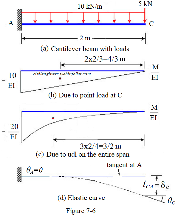
First, draw the bending moment diagram for the beam and divide it by the flexural rigidity, ei, to obtain the moment curvature diagram shown in figure 7.17b. Web first, draw the bending moment diagram for.

Shear and moment diagrams indimg
Ductility is the deformation capacity of a member / structure after the first yield. For a given axial load there exists an extreme compression fiber strain and a section curvature (φ = ε / c.
Slope and Deflection by Moment Area Theorems Civil Engineer Online
The before and after cracking. Create the section using the section designer. Web moment curvature relationships are very important to find out ductility of the structure and the amount of possible redistribution of stresses. Determining.

Learn How To Draw Shear Force And Bending Moment Diagrams Engineering
Web relation between the radius of curvature, r, beam curvature, κ , and the strains within a beam subjected to a bending moment. Web moment curvature relationships are very important to find out ductility of.

Ultimate Guide to Shear Force and Bending Moment Diagrams
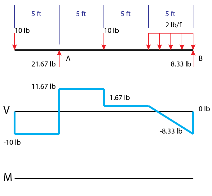
Ductility is the deformation capacity of a member / structure after the first yield. Web the shear diagram crosses the \(v = 0\) axis at \(x = 5l/8\), and at this point the slope of.

7 Example 2 Simplified MomentCurvature for Rectangular Reinforced
The bending moment can thus be expressed as \[m=\int y(e \kappa y d a)=\kappa e \int y^{2} d a\] The before and after cracking. Before starting the diagram, it is crucial to gather all the.
The Ultimate Guide to Shear and Moment Diagrams
Download the degreetutors guide to shear and moment diagrams ebook. The bending moment can thus be expressed as \[m=\int y(e \kappa y d a)=\kappa e \int y^{2} d a\] Chapter 11, page 2 derivation of.
» How to Draw Moment Diagrams ReviewCivilPE
Web if the beam is long and thin, this equation is accurate even when the beam is not in pure bending lecture book: Web | tutorial in this post we’re going to take a look.

Typical MomentCurvature Relationship for Reinforced Concrete Slab
Before starting the diagram, it is crucial to gather all the necessary. Calculating bending moment diagram by hand 1. (3) θ ( x) = ∫ ϕ ( x) d x = ∫ m ( x).
How To Draw Moment-Curvature Diagram 13 april 2022 8122 accesses part of the lecture notes in civil engineering book series (lnce,volume 213) abstract Web relation between the radius of curvature, r, beam curvature, κ , and the strains within a beam subjected to a bending moment. In addition, tcl language features such as variable and command substitution, expression evaluation, and procedures are demonstrated. It is also very important for earthquake resistance and resistance against blasts. Determining shear and moment diagrams is an essential skill for any engineer.