Motor Schematic Drawing
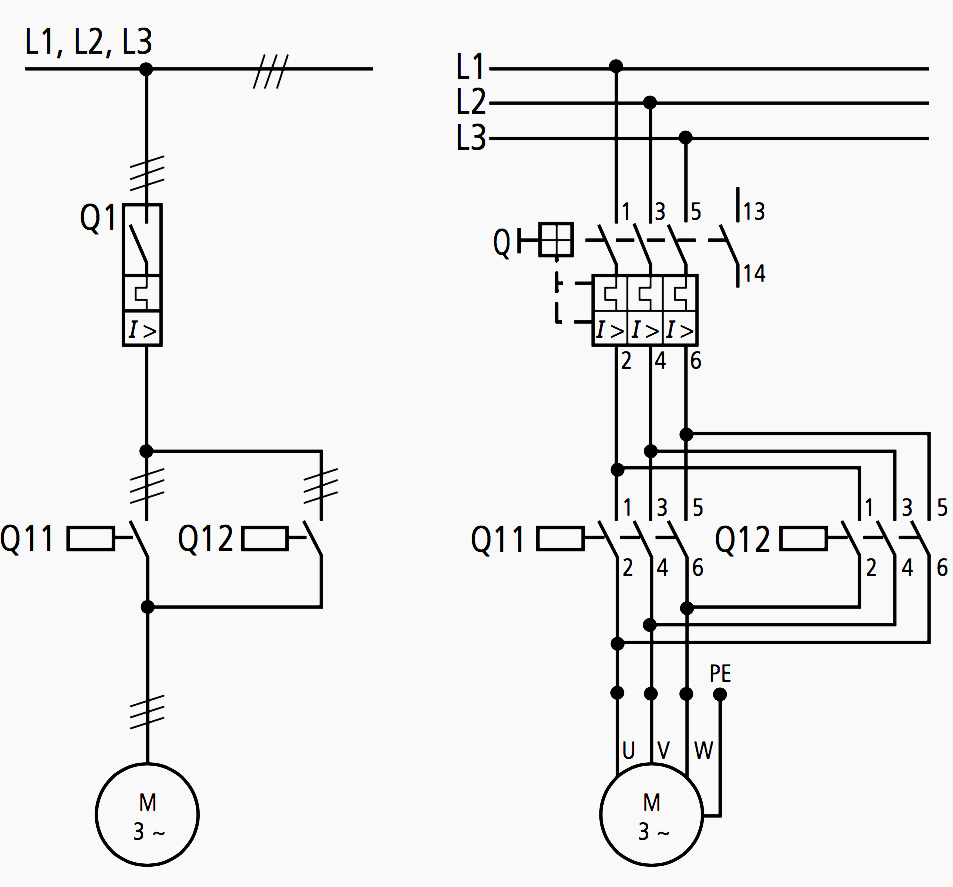
Motor Schematic Drawing - These diagrams are designed to illustrate the flow of electricity and the connections between different parts of the motor. The control circuit may not be at the same voltage as the power circuit. Web 10k views 3 years ago motor control. Basics 9 4.16 kv pump schematic : Power system parameters like voltage, frequency, and starting current.
It is the symbol used for dc shunt motor whose field winding is connected in parallel to the armature winding. O and x are showing direction of electric current. The same sort of thing. You can use a schematic to actually. Second picture is showing the magnetic field generated by stators winding. 4 and 5 wires are fixed. There are a few common symbols used in every diagram, such as lines that represent power sources, arrows to indicate directions of current flow, and circles that represent components.
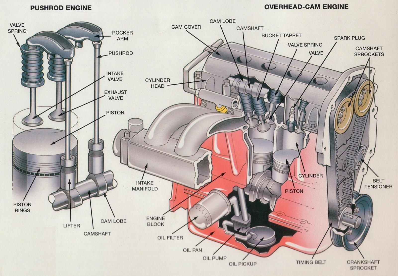
Mechanical Engineering Engine diagram
Basics 14 aov schematic (with block. Web a typical electric motor wiring diagram consists of various symbols and lines that represent the motor, power source, starting mechanism, control circuitry, and other components. 4 and 5.

Motors How to Choose an Electric Motor
This diagrams uses symbols to identify components and interconnecting lines to. Web schematic diagrams are invaluable tools in understanding the inner workings of complex systems, such as electric motors. The original wiring diagram showed the.

Electric Motor Principle, Working, Diagram Explained step by step
This diagrams uses symbols to identify components and interconnecting lines to. Basics 10 480 v pump schematic : The control circuit may not be at the same voltage as the power circuit. The original wiring.
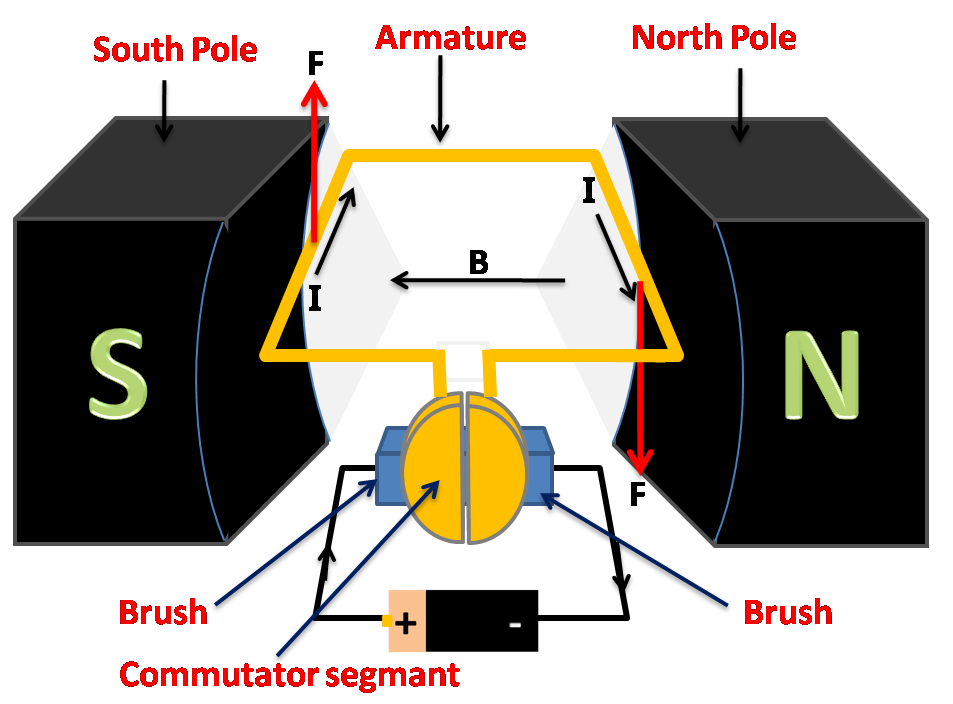
Draw a labelled diagram of an electric motor. Explain its principle and
This symbol represents a single phase ac synchronous motor. These diagrams are designed to illustrate the flow of electricity and the connections between different parts of the motor. Wiring diagrams show the conductive connections between.
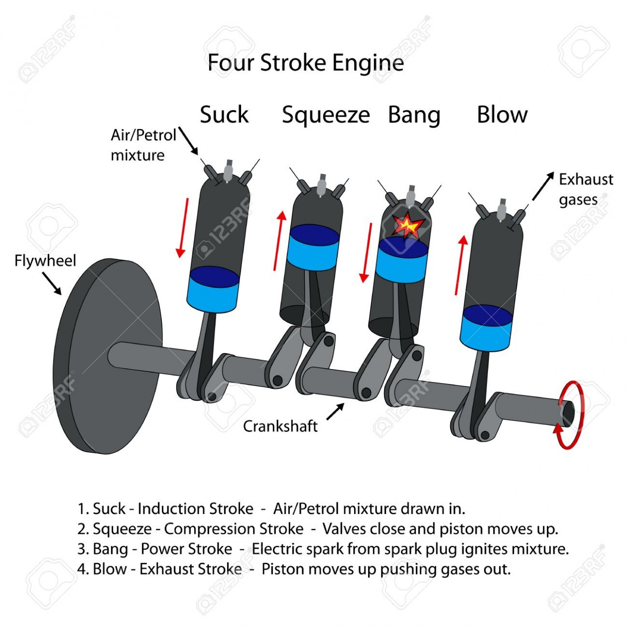
Simple Combustion Engine Diagram Free Image Diagram
Basics 13 valve limit switch legend : Web 10k views 3 years ago motor control. This symbol represents a single phase ac synchronous motor. The load angle) must be always greater than 0° in order.

2 Wire Control Circuit Diagram. Motor Control Basics. Controlling three
4, 5, 6, or 8 wires. Wiring diagrams show the conductive connections between electrical apparatus. Web the image representation of this wiring scheme is easier to visualize. I draw new winding diagram which i had.
All about wiring of electric motors EEP
Both windings are connected to a common direct current supply. When the voltage of the control and power circuits is the same, it is referred to as common control. Basics 14 aov schematic (with block..
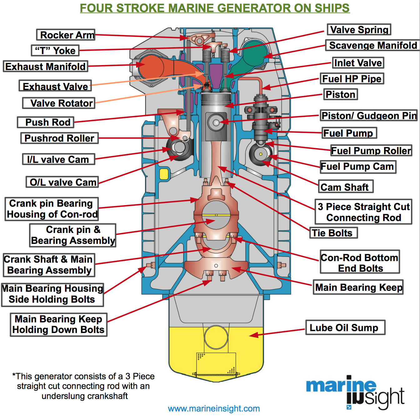
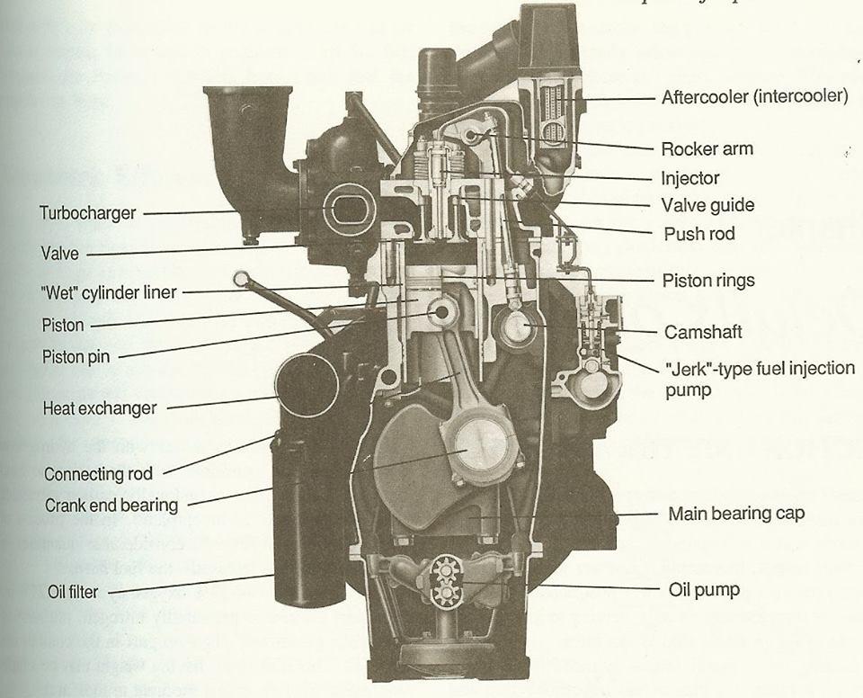
basic for junior marine engineersrammarsea BASIC MARINE DIESEL ENGINES
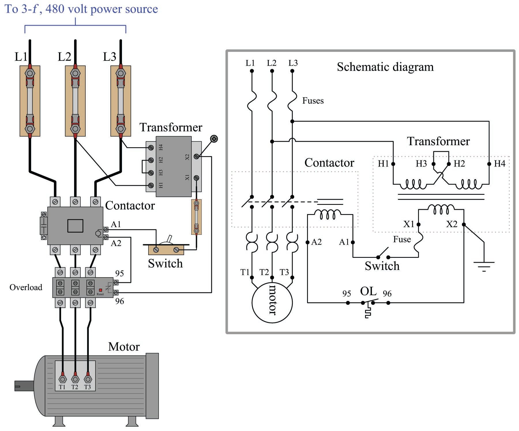
Power is supplied by connecting a step down transformer to the control electronics by connecting to phases l2 and l3. These diagrams provide a visual representation of the electrical circuitry and components, allowing engineers and.
Motor Control Center Schematic Diagram
This symbol represents a single phase ac synchronous motor. Basics 14 aov schematic (with block. Web the electric motor operation is based on the following points: When the pushbutton is released, the closed m 1.
Internal Combustion Engine Block Diagram Free Image Diagram
The original wiring diagram showed the proper arrangement of windings to create a larger wye system in which there are four equal windings between any two leads. Web a typical electric motor wiring diagram consists.
Motor Schematic Drawing 4 and 5 wires are fixed. Instead of wiring diagrams, wiring tables can also be used. Web i remade winding diagram from book, so it fits into my stator. Web 10k views 3 years ago motor control. Web the diagram shows how the commutator (in green) and brushes (in red) work together to let current flow to the electromagnet, and also to flip the direction that the electrons are flowing at just the right moment.